
Owners Manual


13 MS6000-en-GB_V1.5 5/16
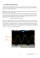
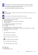
Slope and Level: (Set Trig Type to Edge or Slope) The Slope and Level controls help to define the
trigger. The Slope option determines whether the trigger point is on the rising or falling edge of a signal.
To perform the trigger slope control, press the TRIG button and then select Edge trigger (F1), and use
the Slope button (F3) to select rising or falling. The LEVEL button controls where the trigger point is on
the edge.
Trigger Mode: (Auto, Normal, Single) Select the Auto or Normal mode to define how the
oscilloscope acquires data when it does not detect a trigger condition. Auto Mode performs the
acquisition freely in absence of valid trigger. It allows the generation of untriggered waveforms with
the time base set to 80ms/div or slower. Normal Mode updates the displayed waveforms only when
the oscilloscope detects a valid trigger condition. Before this update, the oscilloscope continues to
display the older waveforms. This mode should be used when it is desired to only view the effectively
triggered waveforms. In this mode, the oscilloscope displays waveforms only after the first trigger.
Single mode will allow you to view a Single sweep of a waveform.
Trigger Coupling: (AC, DC, Noise Reject, HF Reject, LF Reject) Trigger Coupling determines
which part of the signal will be delivered to the trigger circuit. This can help to obtain a stable display
of the waveform. To use trigger coupling, push the TRIG button, select Edge, Pulse, Slope, or O.T.
trigger, and then press F5 for page 2 and select a Coupling option.
Trigger Position: The horizontal position control establishes the time between the trigger position
and the screen center.
Tri
gg
er slo
p
e can be risin
g
or fallin
g
Rising Edge
Falling Edge
Trigger level can be
ad
j
usted verticall
y