
Owners Manual


10 MS6000-en-GB_V1.5 5/16
3.8 Manual Probe Compensation
Upon the first connection of a probe to an input channel, manually perform this adjustment to match
the probe to the input channel. Uncompensated probes may lead to errors or faults in measurement.
To adjust the probe compensation, follow the steps below.
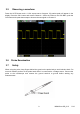
1. Set the switch on the probe to 10X and connect the probe to Channel 1 on the oscilloscope.
Attach the probe tip to the PROBE COMP ~5V@1KHz connector and the reference lead to the
PROBE COMP Ground connector. Press CH1 button and set the Probe attenuation to 10X.
Press the AUTO button and you should see the 1 KHz reference signal.
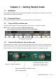
2. Check the shape of the displayed waveform.
3. If necessary, use a nonmetallic screwdriver to adjust the variable probe capacitor until the shape
of the waveform appears to be the same as shown in the above figure. Repeat this step as
necessary for additional probes. Refer to the figure below for adjustment illustration.
Compensated correctly
Overcompensated
Undercompensated