
User Manual

Version 2.0 1/05
7
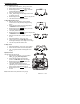
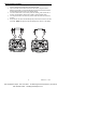
BATTERY INSTALLATION
WARNING: To avoid electric shock, disconnect the test leads from any source of voltage
before removing the battery cover.
1. Turn power off and disconnect the test leads from the meter.
2. Open the rear battery cover by removing two screws (B) using a slotted head
screwdriver.
3. Insert the batteries into battery holder, observing the correct polarity.
4. Put the battery cover back in place. Secure with the screws.
REPLACING THE FUSES
There are three fuses:
Power Supply Fuse
1. The power supply fuse is located in the battery compartment.
2. Remove the two screws to open the battery compartment.
3. Always use a fuse of the proper size and value.
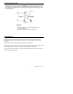
Current Circuit Fuse
1. Fuse protection for the current terminals.
2. If the fuse is blown, the R
C
LED will stay on.
3. The fuse is located under the printed circuit board.
4. There are 4 mounting screws that have to be removed.
5. Two screws are located under the black feet on the bottom of the unit.
6. The other two screws are located in the battery compartment.
7. Remove the battery compartment door and the batteries to access these screws.
8. Always use a fuse of the proper size and value.
Potential Circuit Fuse
1. Fuse protection for the potential terminals.
2. If the fuse is blown, the R
P
LED will stay on.
3. The fuse is located under the printed circuit board.
4. There are 4 mounting screws that have to be removed.
5. Two screws are located under the black feet on the bottom of the unit.
6. The other two screws are located in the battery compartment.
7. Remove the battery compartment door and the batteries to access these screws.
8. Always use a fuse of the proper size and value.
Test Equipment Depot - 800.517.8431 - 99 Washington Street Melrose, MA 02176
FAX 781.665.0780 - TestEquipmentDepot.com