
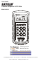
User Manual


Setting Absolute Hi/Lo Limits
The Hi/Lo limits set allows the user to enter an upper and lower limit value into memory
for comparison to the measured value.
1. Press the SET key and then the Hi / Lo LIMITS key. The upper limit “ “ indicator
will flash and the previously stored upper limit will appear with the first digit flashing.
2. Set the value of the flashing digit by pressing the appropriate numeric key. The
adjustment selection will then proceed through each digit from left to right.
3. Press the - 0 key after the last digit is set to change the value of the sign to negative
or positive.
4. Press the “ENTER” key to store the value and continue on to the lower limit
adjustment.
5. The lower limit “ “ indicator will flash and the previously stored lower limit will
appear.
6. Adjust the limits as described for the upper limit and press the “ENTER” key when
complete.
Setting % Tolerance Limits
The % tolerance set allows the user to enter an upper and lower percentage limit into
memory for comparison of the measured value to a reference value.
1. Press the SET key and then the TOL key. The “TOL” indicator will flash and the
previously stored reference will appear with the first digit flashing.
2. To adjust the reference, set the value of the flashing digit by pressing the
appropriate numeric key. The adjustment selection will then proceed through each
digit from left to right.
3. Press the “ENTER” key to store the value and continue on to the % upper limit
adjustment. The upper limit “ “ indicator will flash and the previously stored upper
% limit will appear.
4. Adjust the % limit as described for the reference value and press the “ENTER” key
when complete. The lower limit “ “ indicator will flash and the previously stored
lower % limit will appear.
5. Adjust the lower % limit and press “ENTER” when complete.
Setting a Relative Reference
The relative set allows the user to store a relative reference value into memory for later
use in the REL mode.
1. Press the SET key and then the REL key. The “ ” indicator will flash and the
previously stored reference will appear with the first digit flashing.
2. To adjust the reference, set the value of the flashing digit by pressing the
appropriate numeric key. The adjustment selection will then proceed through each
digit from left to right.
3. Press the - 0 key after the last digit is set to change the value of the sign to negative
or positive.
4. Press the “ENTER” key to store the reference value.
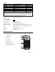
PC INTERFACE
The Model 380193 LCR Meter includes a PC interface feature for use with the supplied
Windows
TM
software. The interface allows the user to:
View measurement data in real time on the PC
Save, Print, and Export measurement data.
Set standard and high / low limits for data analysis
Generate calibration reports in spreadsheet format
Plot SPC (statistical process control) analyses
Database compatibility (supports ODBC) for use with: SQL server, Access
TM
,
and other database utilities
Instructions for use of the PC interface are included on the supplied Program Disk and are
beyond the scope of this operation manual. For complete details and instructions refer to
the HELP file on the supplied Program Disk.
Test Equipment Depot - 800.517.8431 - 99 Washington Street Melrose, MA 02176
FAX 781.665.0780 - TestEquipmentDepot.com