
User Manual

VT30-US-EN-V4.0-3/12
4
Operation
Always test the meter on a known live circuit before taking measurements
Voltage Measurement
1. Note: The voltage tester will turn on automatically when voltages higher than 4.5V
AC/DC are detected.
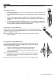
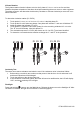
2. Touch the positive (L2) and negative (L1) test leads to the device or circuit under
test.
3. If the voltage is higher than 4.5V AC/DC, the LCD will light and display the
reading. The stepped voltage bargraph scale in the display will also indicate the
reading.
4. For AC voltages, the
LED will light and the “AC” icon will appear in the display.
For DC voltages, the “DC” icon will be displayed. If the DC voltage is negative, a
minus sign will be displayed before the digital readout.
Single Lead AC Voltage Detection
To check for the presence of voltage (between 100V and 480V) using only the
positive test lead (L2), touch the lead to the device or circuit under test. If voltage
is present, the
LED will light.
Note: In this mode, the actual voltage is not displayed; only the presence of
voltage is detected.
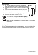
Low Impedance Voltage Measurement
Due to the lowered internal impedance, capacitive voltage is suppressed
so that the reading shows the actual voltage applied. This can be used to
quickly identify phantom voltages.
1. Hold the two test tips on the measuring points to be tested.
2. Press the two low impedance test buttons simultaneously.
3. The Low Impedance LED will light and the applied voltage will be
displayed on the LCD.
Note: The maximum duty cycle in this mode is 5 seconds for voltages up
to 250V and 3 seconds for voltages up to 690V. Allow 10 minutes
between each reading.
Note: Measuring from hot to ground may trip any GFCI equipped circuits.