User's Guide 3-Axis G-Force Datalogger Model VB300
Introduction Congratulations on your purchase of the VB300 G-Force Datalogger. The Model VB300 can measure and record shock and vibration (acceleration) readings over its ± 18g measurement range. This device will record 3-axis g-force and related peaks to provide a history of shock and vibration conditions. The real time clock provides time stamps for all data.
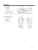
Description Meter Description 1. USB connector 2. RECORD LED 3. ALARM LED 4. Datalogger Start / Stop Button 5. Axis reference diagram Note: Battery compartment access screws (2) located on rear of unit. Refer to the battery installation section for further details. Pedestal Mount Description 1. Mounting screw holes 2. Swivel latch 3. Swivel latch lock 4. Mounting magnets FRONT VIEW 3 REAR VIEW VB300 V1.
Mounting the VB300 The VB300 fits securely in the supplied mounting pedestal. Unscrew the pedestal latch and snap the VB300 into the pedestal. Secure the latch and follow one of the mounting methods below. There are three mounting methods for affixing the pedestal to the area under test: 1. Magnetically: Powerful magnets are built into the rear of the pedestal 2. Adhesive: Use glue (not supplied) to affix the pedestal to the area under test 3.
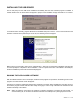
Datalogging Software Program INSTALLING THE DATALOGGER SOFTWARE Install the supplied WindowsTM PC Datalogger Software by placing the supplied program disk in the PC’s CD-ROM drive. If the installation program does not automatically open and provide on-screen prompts (as shown in diagram below), open and browse the CD-ROM drive, then find and double-click on the SETUP.EXE file included on the program disk. Follow the on-screen prompts as shown below to complete the installation.
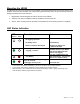
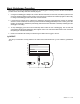
INSTALLING THE USB DRIVER The PC will prompt for the USB Driver installation immediately after the main software program is installed. A window similar to the one shown below will appear to prompt for the installation. Simply click INSTALL to continue. To install the driver manually, plug the VB300 into an available USB port on the PC.
Basic Datalogger Operation This section covers only the starting and stopping of the Datalogger’s recording functions. All other information is provided in the HELP utility within the software program. 1. Configure the Datalogger’s sample rate, motion detection threshold, record mode, LED flash cycle and more using the supplied software program. Refer to the instructions included in the software program’s HELP utility to configure the datalogger and to otherwise use the software. 2.
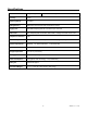
Specifications Acceleration Range: ± 18g Resolution: 0.00625g Accuracy ± 0.
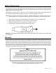
Battery Replacement The VB300 does not lose its stored readings when the battery expires or when the battery is replaced. The data logging process will however be stopped and cannot be re-started until the battery has been replaced and the logged data has been downloaded to PC. The battery life is rated for approx. 1000 hours. If in doubt, replace the battery before logging critical data. Use only 3.6V lithium batteries. Before replacing the battery, remove the datalogger from the PC.