User Manual Micro-Ohmmeter Model UM200 Additional User Manual Translations available at www.extech.
Introduction Thank you for selecting the Extech Model UM200. This device is shipped fully tested and calibrated and, with proper use, will provide years of reliable service. This device is shipped fully tested and calibrated and, with proper use, will provide years of reliable service. Please visit our website (www.extech.com) to check for the latest version and translations of this User Manual, Product Updates, Product Registration, and Customer Support.
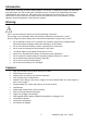
Meter Description Front Panel 1. LCD: 6000 count LCD with Backlight. 2. ▲ button: In SETUP mode, press the ▲ button to increment value by 1. Press and hold the ▲ button for over 2 seconds to increment value swiftly. In Recall mode, press the ▲ button to display the next stored data location. 3. SELECT button: In SETUP mode press the SELECT button to select HI (Limit) or LO (Limit) or display cable resistance per foot or meter 4. ▼ button: In SETUP mode, press the ▼ button to decrement value by 1.
8. FEET / METERS button: In cable length mode, press the FEET / METERS button to select units of Meter (M) or Feet (FT). 9. LED: If the light is on, measurements are for both inductive and resistive materials. If the light is off, measurements are for resistive materials only. 10. Power error LED: If the light is on, measurement errors may be caused by one of the following reasons: Low battery voltage Blown fuse Measuring a device with electrical potential (voltage).
Rear Panel 1. Communication port 2. Stand. 3. Battery cover 4. Battery cover screw Top Panel 1. C1 Alligator Clip Terminal or 4-wire Test Leads Terminal. 2. P1 Alligator Clip Terminal or 4-wire Test Leads Terminal. 3. P2 Alligator Clip Terminal or 4-wire Test Leads Terminal. 4. C2 Alligator Clip Terminal or 4-wire Test Leads Terminal. 5. - Kelvin Clip Terminal. 6. +Kelvin Clip Terminal. 7. POWER for the input of AC adaptor. 5 UM200-en-GB_V1.
Operation Note: 1. The battery is charged before shipment, operation when first received is permitted. 2. When in Resistance mode, zero the range before making measurements. 3. After the START/STOP button is pressed to start measurement, the unit cannot be stopped until the first measurement is completed. 4. When the LED light with inductance symbol is on, this indicates the measurement is for both resistive materials and inductive materials.
LED ON (6, 60, 600 and 6000Ω ranges) Resistance measurements with the 1. 2. 3. 4. 5. 6. 7. Connect the test leads to the meter. Turn the switch to a proper measurement range. Five dash lines (-----) will be shown in LCD. Zero the range before making measurements. Connect the Kelvin clips together and press the START / STOP button then press the Zero button. The reading should read zero Ohms. Connect the test leads to the device under test. The LCD will continuously display the value of the resistance.
Alarm Function Press the button to enable the alarm function after the HI and LOW limits are set. The symbol will be displayed in the LCD. If the resistance measured falls within the range of HI and LO limits, a symbol of PASS is shown in the LCD. If not, the buzzer will beep to indicate a fail. If the reading is OL, the alarm function is temporarily disabled until a reading is obtained. Alarm HI, LO, or Resistance per unit Setup 1. Turn the rotary switch to SETUP. 2.
Recalling pre-stored Ω/LENGTH data There are up to 20 pre-stored Resistance per unit values stored into memory. These values can be recalled and used for cable length measurement. 1. In SETUP mode, press the RECALL button to recall pre-stored data. 2. Press the SELECT button until the resistance per unit values appear. 3. Press the RECALL button to step through the stored values. 4. Turn the rotary switch to the proper range and press START to measure the cable length.
Battery Charging 1. The battery should be recharged when the low battery icon appears in the display, after extended use or after a long period of storage. 2. Connect the AC Adaptor to the meter. 3. Turn the rotary switch to an ON position NOTE: The battery will not charge with the rotary switch in the OFF position Battery Replacement The charging circuit is designed only for the lithium battery included with the meter.
Specifications General Specifications LCD Display: Power Source: 60000 count LCD with Backlight Rechargeable Lithium Battery, 3400mAh (11.1V) (Part # BATT-111V) Battery Recharge Time: 10 hours Battery Charge: AC 110V or 220V input, DC 15V / 1 to 3A output Please note the polarity of the DC output Dimensions: 10.1x6.1x2.25” (257 x 155 x 57mm) Weight: 40.