USER GUIDE 12-Channel Thermocouple Datalogger Model TM500
Introduction Congratulations on your purchase of the Extech TM500 Thermometer, an SD Logger Series meter. This meter displays and stores temperature readings from up to twelve (12) Type K, J, T, R, E, or S thermocouple temperature probes. Logged data readings are stored on an SD card for transfer to a PC. In addition, an RS232 port allows data streaming to a PC. This meter is shipped fully tested and calibrated and, with proper use, will provide years of reliable service.
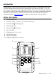
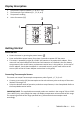
Display Description 1. 2. 3. 4. Temperature Channel number (1 – 8 or 9 – 12) Thermocouple Type indicator (K, J, T, E, R, or S) Temperature reading Units of measure (C/F) 2 1 K CH1 CH5 CH2 CH6 CH3 CH7 CH4 CH8 3 F 4 Getting Started Power ON‐OFF Power the meter by pressing the power button . Press and hold the power button for at least 3 seconds to power OFF the meter. This meter is powered by eight (8) 1.5VDC ‘AA’ batteries or by optional AC adaptor.
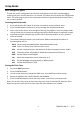
Setup Mode Basic settings at a glance To view the current configuration of the meter with regard to time, date, and datalogging sampling rate press the SET button for > 4 seconds. The meter will now display the configuration menu. The Setup page reverts to the temperature window in approximately 8 seconds if there are no button presses. Accessing the Setup mode 1. 2. 3. 4. 5. Press and hold the SET button for at least 4 seconds to access the Setup menu.
Setting datalogging Loop mode This meter can be set to record temperatures for the same time every day. Example – record temperatures every day from 9:00 to 13:00 1. 2. 3. 4. 5. 6. 7. 8. Access the LooP parameter. Press the ENTER button. Set the Start Hour (0‐23) and press ENTER. Set the Start Minute and press ENTER. Set the Stop Hour and press ENTER. Set the Stop Minute and press ENTER. Press the up or down arrow to indicate YES and press ENTER.
Set the Temperature Units of Measure (°C or °F) 1. 2. 3. Access the t‐CF parameter. Use the arrow buttons to select °C or °F. Press ENTER to confirm setting. Press the ENTER button to exit to the Setup mode. Press ESC to exit setup mode. Setting the Datalogger Sampling Time (Rate) 1. 2. 3. 4. Access the SP‐t parameter. Use the arrow buttons to select the desired sampling rate. The available settings are: 0, 1, 2, 5, 10, 30, 60, 120, 300, 600, 1800, and 3600 seconds. Use ‘0’ for manual logging mode.
Measurements and related features Basic Thermocouple Mode Thermocouples are connected at the top of the meter to the jacks labeled T1 through T12. Select the thermocouple type (J, K, etc.) to match the thermocouple type used. In normal thermocouple mode the meter will simultaneously display the temperature for thermocouples T1 through T12. Dashes are displayed if a thermocouple is not connected or if the measurement is out of range.
4. 5. switched on (when the MAX‐MIN button was first pressed). To delete the MAX value, press the HOLD button. The display will show just the REC icon. Press the REC button again to view the current MIN readings (MIN icon appears). The readings on the display are now the lowest readings encountered since the REC icon was switched on (when the MAX‐MIN button was first pressed). To delete the MIN value, press the HOLD button. The display will show just the REC icon.
Datalogging and PC Interface Types of Data Recording Manual Datalogging: Manually log up to 99 readings onto an SD card via push‐button press. The sample rate must be set to 0 to implement this mode. Automatic Datalogging: Automatically log data onto an SD memory card where the number of data points is virtually limited only by the card size. Readings are logged at a rate specified by the user from 1 to 3600 seconds.
Automatic Datalogging In automatic datalogging mode the meter takes and stores a reading at a user‐specified sampling rate onto an SD memory card. The meter defaults to a sampling rate of two seconds. To change the sampling rate, refer to the Setup Mode section (the sampling rate cannot be ‘0’ for automatic datalogging): 1. Press REC button to turn on record mode. The REC icon will appear in the upper left corner of the display. 2. Start an automatic Datalogging session by pressing the LOGGER button. 3.
SD Data Card to PC Data Transfer 1. 2. 3. 4. Complete a datalogging session as detailed in above in the previous sections. Hint: For the first test, simply record a small amount of test data. This is to ensure that the datalogging process is well understood before committing to critical datalogging. With the meter switched OFF, remove the SD Card. Plug the SD Card directly into a PC SD card reader.
Battery Replacement and Disposal When the low battery icon appears on the LCD, the batteries must be replaced. Several hours of accurate readings are still possible in this condition; however batteries should be replaced as soon as possible: Remove the two (2) Phillips screws from the rear of the meter. Remove and safely place the battery compartment and screws where they will not be lost. Replace the eight (8) 1.5V ‘AA’ batteries observing polarity.
Specifications General Specifications Display Backlit LCD; LCD size: 82×61mm (3.23×2.40") Status indicators Over‐range (‐‐‐‐) and low battery Measurement Channels T1 to T12 Sensor types Thermocouple types: K, J, T, E, R, and S Measurement Units °C / °F Offset Adjustment To adjust the zero temperature deviation value Linearity Compensation Linear compensation for the full range Datalogger Sampling Rate AUTO LOGGING: 1, 2, 5, 10, 30, 60, 120, 300, 600, 1800, 3600 seconds.
Thermocouple Input (types K, J, T, E, R, and S) Sensor Type Resolution 0.1°C Type K 1°C 0.1°F 1°F 0.1°C Type J 1°C 0.1°F 1°F 0.1°C Type T 0.1°F 0.1°C Type E 0.1°F 1°F 1°C Type R 1°F 1°C Type S 1°F Range ‐100.0 to ‐50.1°C ‐50.0 to 999.9°C 1000 to 1300°C ‐148.0 to ‐58.1°F ‐58.0 to 999.9°F 1000 to 2372°F ‐100.0 to ‐50.1°C ‐50.0 to 999.9°C 1000 to 1150°C ‐148.0 to ‐58.1°F ‐58.0 to 999.9°F 1000 to 2102°F ‐100.0 to ‐50.1°C ‐50.0 to 400.0°C ‐148.0 to ‐58.1°F ‐58.0 to 752.0°F ‐100.0 to ‐50.1°C ‐50.