USER GUIDE Model TKG250 Ultrasonic Thickness Gauge
Extech Instruments WARRANTY FLIR Systems, Inc. warrants this Extech Instruments brand device to be free of defects in parts and workmanship for two years from date of shipment (a six month limited warranty applies to sensors and cables). If it should become necessary to return the instrument for service during or beyond the warranty period, contact the Customer Service Department for authorization. Visit the website www.extech.com for contact information.
TKG250 Ultrasonic Thickness Gauge LIABILITY Ultrasonic testing is a function of using the proper equipment (electronics, transducer, cable and couplant combination) for the inspection and a qualified operator who knows how to use this manual, the instruments and all calibration procedures. The improper use of this equipment, along with the improper calibration can cause serious damage to components, factories, facilities, personal injury and even death.
Extech Instruments Table of Contents Table of Contents ........................................................................................................... 4 1 Getting Started ............................................................................................................ 6 About the TKG250 Wave ............................................................................................. 6 Probe Zero ........................................................................................
TKG250 Ultrasonic Thickness Gauge Using the Fast Option................................................................................................. 26 Using the Gain Option ................................................................................................ 29 Using the Diff Option .................................................................................................. 31 Using the Alarm Option ......................................................................................
Extech Instruments 1 Getting Started About the TKG250 Wave The TKG250 is a portable, digital, handheld thickness gauge and is specifically designed to measure the remaining wall thickness of primarily steel structures.
TKG250 Ultrasonic Thickness Gauge Probe Zero When turning on the TKG250, the gauge does an automatic zeroing of the transducer thus eliminating the need for an on-block zero. It will also electronically zero the transducer upon power up and at a particular time during normal operation. This feature ensures the transducer is working in accordance with electronic zeroing procedures. This feature is particularly important on high temperature materials and when the transducer becomes worn.
Extech Instruments Up arrow key Down arrow key Left arrow key Right arrow key On/Off symbol (under the F1 key) OK key F1 key F2 key F3 key Function Keys Function keys, or F keys, such as F1, F2, and F3 have various gauge functions and may change depending on the display screen. View the bottom of the display screen for the function that corresponds with the appropriate F key. For example, F1 may correspond with the Save function, F2 with the Freeze function, or F3 with the Directory function (Dir).
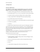
TKG250 Ultrasonic Thickness Gauge Color Waveform in Echo-to-Echo, filename, id, minimum, large thickness value, Echo-to-Echo, range, echoes, blanking, gain, rectification, battery life, save, freeze and directory. RF in Zoom mode “Z” F1 F2 F3 The top part of the display screen shows the File name, ID number, AA, and 0001 for grid column and row.
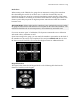
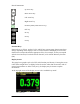
Extech Instruments F1 F2 F3 Using the Battery Pack Monitoring the Battery Charge from the Display Screen The TKG250 constantly displays the percent battery life on the bottom right hand corner of the measurement display screen. When the gauge gets below 10 %, the indicator will turn from green to red and a 5% it will flash. Note: You should power down the TKG250 to ensure any saved data is stored internally.
TKG250 Ultrasonic Thickness Gauge 2 Basic Gauge Operations Power on the Gauge To power on the TKG250 thickness gauges follow these steps: 1. Press and hold the F1 key for more than 3 seconds. The power symbol is under the F1 key printed on the keypad as shown below. Power symbol under the F1 key 2. The company information screen will appear on the display screen of the thickness gauge. 3.
Extech Instruments Performing a Reset You can reset the gauge settings back to the default settings by performing a gauge reset. Note: Performing a reset permanently deletes all of the saved parameters from the gauge and replaces the settings with default values. To perform a reset, follow these steps: 1. From the Home screen, press the F1 – Reset key. The following Reset screen appears: 2.
TKG250 Ultrasonic Thickness Gauge If you want to exit this screen press either the F1 – Exit key or F3 – No key to take no action and return to Home screen. 3. Press the F2 – Yes key to perform a Database reset. After performing a Database Reset, the Home screen appears automatically. Parameter Reset Performing a Parameter Reset restores default parameters to the factory settings. To perform a Parameter Reset, follow these steps: 1. From the Home screen, press the F1 – Reset key. The Reset screen appears.
Extech Instruments Database/Parameter Reset Performing a Database/Parameter Reset clears all the files in the database and keeps the first three Linear, Row increment and Col increment database files with cleared readings. All the user created files in the database will be deleted and the default parameters will be restored at the same time. This selection is the equivalent of performing MASTER RESET on the instrument, restoring original factory setting.
TKG250 Ultrasonic Thickness Gauge About Screen You can find information about the TKG250 thickness gauge such as the model number, version number and contact information from the gauge‟s About screen. To go to the About Screen, follow these steps: 1. From the Home screen, press the F1 – Reset key. The following Reset screen appears: 2. Press the F3 – About key. The About screen appears showing company contact information. 3. Press the F1 – Exit key to return back to Reset selection screen.
Extech Instruments 3 Calibrating the Gauge and Making Measurements Calibrating is the process of adjusting the gauge for a specific material and transducer before testing material to make sure that all measurements are accurate. You must always calibrate before measuring material for standard accuracy. To measure a thickness of unknown material you need to know the velocity of the sound in the unknown material.
TKG250 Ultrasonic Thickness Gauge Velocity and Zero Calibration If you have a test step block of known thicknesses but unknown material, then you can calibrate the zero and velocity of the sound in the unknown material by measuring the time of flight from the main-bang to the first back echo for thinner step and thicker step. To calibrate both: velocity and zero at the same time, first go to the Cal mode as shown in Velocity Calibration Only section.
Extech Instruments Automatic Zero To perform an Automatic Zero or Auto Zero, you must first select a transducer option from the Xducer selection screen and press the OK key. To continue the Auto Zero, follow these steps: 1. Follow the instructions given on each display screen; the first of which will prompt you to wipe off any couplant from the transducer and wait three seconds. The waiting time is shown in the changing pie-clock graphic on the display screen. 2.
TKG250 Ultrasonic Thickness Gauge Measurement Mode with a Datalogger The TKG250 thickness gauge is equipped with a datalogger, and the display screen in Measurement mode will look like the screen below: To continue in Measurement mode, follow these steps: 1. Press the F1 key to select the Save option. (See: Save section for datalogger version.) 2. Press the F2 key to select the Freeze option. (See: Freeze section.) 3. Press the F3 key to select the Dir (Directory) option. (See: Directory section.) 4.
Extech Instruments 4 Adjusting parameters in A-Scan mode: In addition to changing parameters via the Menu OK key, you can also adjust the following parameters while in A-Scan: Units (in, mm, usec) Alarm (high, low, high-low, high vib, low vib, high-low vib, off) Gain (AGC or manual in 1 db from 20 dB as min and 94 dB as Max) Rectify (RF, Full Wave, Half + or Half -) Range (.5,1,2,5,10 and 20 inch or 12.7, 25.
TKG250 Ultrasonic Thickness Gauge Rectify Highlighted Echo-to-Echo Highlighted Range Highlighted Gain Highlighted NOTE: Pay close attention when turning on Echo-to-Echo as thickness readings will not be accurate with Echo-to-Echo on versus off if you do not re-calibrate. You will also see an Echo-to-Echo cursor on the bottom of the screen to indicate where the measurements are being made.
Extech Instruments 5 Using Setup Mode on the Gauge The following modes are available: To select Measurement mode, follow these steps: 1. Press Menu OK to get to Measurement mode. 2. Use the up and down arrow keys to select the Measurement option and press the OK key. The following Setup choices are available: 22 TKG250- EN V2.
TKG250 Ultrasonic Thickness Gauge 3. Use the up and down arrow keys to select any of the setup parameters available and press the OK key to change the setting. You can also change the setting using the “Quick Access mode”. To do this, simply use the left and right key (indicated in the top right hand of the display screen) to change the setting of the highlighted parameter. The entire list of available Measurement parameters are as follows: Note: Hold is off screen in the above image.
Extech Instruments Backlight USER Color ON LEFT HAND Flags, Grid, Text, Waveform, Background Some color changes are dynamic, meaning you will see the changes as you make the change; examples include Flag, File, ID. Others, such as waveform and background, can only be seen once the change is made and you return to the screen. Note: the TKG250 will not allow the superimposition of two simultaneous colors.
TKG250 Ultrasonic Thickness Gauge The entire list of available clock setup options are as follows: TIME FMT 12 HR DATE FMT MM/DD MINUTE 21 HOUR 01 PM DAY 01 MONTH 01 YEAR 2005 To set the time and date, follow these steps: 1. Select Clock option from the Initial Setup screen. The following is an example of what the clock setup screen might look like depending on the previous setup. To change the Time Format, select TIME FMT using up/down arrow keys.
Extech Instruments 4. To set the Hour, select the HOUR option using up/down arrow keys. Use left/right arrow keys to decrease/increase the hour value. If time is set in 12 HR format, the available hour values are from 00 AM to 11 PM. If time is set in 24 HR format, the available hour values are 00 to 23. 5. To set Day, select the DAY option using up/down arrow keys. Use left/right arrow keys to decrease/increase the day value. You can set the day value from 01 to 31. 6.
TKG250 Ultrasonic Thickness Gauge 1. Use the up and down arrow keys to highlight the Fast option and press the OK key. Or once Fast is highlighted, use Quick Access mode by pressing left or right arrow key as indicated in the top right corner of the display screen. The following parameters are available: 2. Use the up and down arrow keys to select the desired parameter and press the OK key. 3. Press OK key again to accept and return to Measure mode.
Extech Instruments Helpful Hint: When using the FASTMIN mode, if you press the F2 key “Freeze” prior to LOS, the gauge will display the last minimum prior to the LOS so that the actual couplant on the end of the transducer is not registered as a legitimate minimum reading.
TKG250 Ultrasonic Thickness Gauge Note: The LOS flag indicates the LAST MAX or the LAST MIN value and is shown based on the FastMax or FastMin setting. To reset the tracking of LAST MAX and LAST MIN measured value press the OK (Menu) key. Using the Gain Option From the Measurement Screen, gain refers to an increase in signal power (echo height) and is typically measured in decibels (dBs). The Gain function is useful for setting a reference level where by making it easier to add or subtract gain.
Extech Instruments The Gain selection is available from the Measurement screen to either AGC (Auto Gain Control) or Manual (1dB step) for the waveform models. You can also adjust the gain for waveform gauges from the live A-Scan. To adjust gain during a live A-Scan, press the right or left arrow until gain is highlighted, then use the up or down arrow or F2 to return to AGC and F1 when done.
TKG250 Ultrasonic Thickness Gauge Using the Diff Option From the Measurement screen, there are two Diff options, which include: Diff ABS: Absolute where the gauge will display a thickness value as an absolute number of what has been entered. For example, diff abs = 0.500” and the real thickness is 1.000 inch, the display will show diff abs 0.500. If the real value is 0.300, the gauge will display, -0.
Extech Instruments Green echoes=good Red echoes = tripped alarm The Alarm option is available from the Measurement screen. 32 TKG250- EN V2.
TKG250 Ultrasonic Thickness Gauge 1. Use the up and down arrow keys to highlight the Alarm option and press the OK key or you can use Quick Access mode by using the right or left keys once Alarm is highlighted from the Setup mode. If you are using the non-datalogger version you can also press the F1 (Alarm) key to go directly to the Alarm option without having to go through the Setup Mode. The following ALARM selections are available: 2.
Extech Instruments press the OK key to continue. 3. Use the same steps from above to set the Alarm Low settings. 4. Setting the % for caution. In this mode, the % entered based on the high and low set points will cause the waveform and F2 to light up yellow: Note: The Low Alarm limit will not go beyond the High Alarm limit. 5. When you are finished adjusting the setting, press the OK key to return to Measure mode. 34 TKG250- EN V2.
TKG250 Ultrasonic Thickness Gauge Setting the Visual and Audible Alarm The Visual Alarm conditions can be viewed from either a red, yellow or green LED that lights up under the F1, F2, or F3 keys on the keypad. As an example, when using the 5 step English test block with thicknesses of 0.100, 0.200, 0.300, 0.400 and 0.500 inches, if you enter alarm high-low you will first need to enter the high value. Enter 0.500 and press enter. Next you will need to enter the low value of 0.100 in.
Extech Instruments Visual and Audible Alarm is enabled. The letter A (Alarm) appears in the alarm icon Visual, Audible, and Vibrating alarm enabled .)) symbol appears next to the alarm icon. The letter H (High) appears in the alarm icon Alarm condition has occurred meaning the measured reading is greater than the High Alarm limit. The letter H (High) appears in the alarm icon. The screen above has the Vibrating alarm enabled as the .)) symbol appears next to the alarm icon.
TKG250 Ultrasonic Thickness Gauge Rectification Mode Adjustments: Lastly, in Echo-to-Echo, sometimes using various rectification modes can “clean up” the signals so you are reading the proper echoes.
Extech Instruments The first Read line on the baseline is referred to as the Main Bang Blank while the second red line is referred to as the Blank After First Received echo. The white line represents the measured time interval between the two correct echoes. 38 TKG250- EN V2.
TKG250 Ultrasonic Thickness Gauge 6 Special Gauge Functions The TKG250 thickness gauge has many special functions that go beyond the basics. This section will discuss these special gauge functions in detail. Using the Save Option You are able to save your data via the Save option. Please note, the save key can appear over either the F1 or F3 keys depending on how the user prefers to setup the gauge. See section… To use the Save option, follow this step: 1.
Extech Instruments reading will be stored at the ID location [Linear], [Row], [Col] without notes. (See: Directory selection for file type details.) Using the Freeze Option You can freeze your data via the Freeze option. To use the Freeze option, follow these steps: 1. From the Measurement mode screen, press [F2] (Freeze). The following screen comes up after pressing [F2] (Freeze) whereby showing the flag “Freeze” under the thickness reading. You are now in Freeze mode.
TKG250 Ultrasonic Thickness Gauge 41
Extech Instruments 7 Using the Datalogger Directory Mode To use the datalogger Directory mode, follow these steps: You can either press F3 if Min or Max clear is not present or press the Menu OK key and view this screen: Then you will see this screen: Choosing a file: Naming a file: type in name, press F3 when done 42 TKG250- EN V2.
TKG250 Ultrasonic Thickness Gauge Next you will need to use the up and down keys to determine the file type and amount of readings stored per file.
Extech Instruments Use the right arrow to change from linear to grid files, 2D, 3D and boiler files. Use the down arrow to select end row and/or end column. The Maximum number of readings per file is 5,000 and 160 A-Scan. The gauge will dynamically re-calculate the size based on row end times column end. : 1. From the Measurement mode screen press [F3] (Dir) to select the Directory mode.
TKG250 Ultrasonic Thickness Gauge 3. Press the OK key to select a file in the directory view. 4. To create a custom file see Creating Custom Files section. 5. To review thickness readings, see Reviewing a File section. 6. To rename custom file, see Renaming a File section. 7. To clear an entire file, see Clearing a File section. 8. To clear selected readings from a file, see Reviewing a File section. 9. To create copy of the existing file structures, see Copying a File section. 10.
Extech Instruments For Columns ending at C means 3 columns are required and the maximum Row allowed is limited to 5000 / 3 = 1666. If you create a new GRID file with END COLUMN = Z, then the maximum ROW you can slew up to is limited to 5000/26 = 192.
TKG250 Ultrasonic Thickness Gauge A COLINC file with END COLUMN value ZZ will have ID increments as follows: A,1 to ZZ,1 then A,2 to ZZ,2 then . A,7 to ZZ,7 Creating a new File To create a custom file in the datalogger, follow these steps: 1. Press [F3] (Dir) from the Measurement mode screen. The following screen appears: 2. Use the up and down arrow keys to highlight the next Empty file in the list.
Extech Instruments 3. Press the OK key and the following screen appears: 4. Use the up, down, left, and right arrow keys to select the characters of the filename. Press the OK key to accept the selected characters. If you make an error, press [F2] (Del) to delete the last character of the entered filename. 5. Press [F3] (Done) when you are finished entering the filename. The following screen appears: 6. Use the left and right arrow keys to select a file type: LINEAR, ROWINC or COLINC.
TKG250 Ultrasonic Thickness Gauge Selecting a Custom Linear File When you select a LINEAR file format the following screen appears displaying the maximum reading you can store in the LINEAR file. With the extended memory, you can store up to 100,000 readings allowing you more total files. Pressing the F3 (Done) key again will take you to the Measure mode displaying the new filename in the top left corner and the next ID location in the top right corner.
Extech Instruments When you are finished selecting END ROW and END COL values, press F3 (Done). The display will go back to Measure mode, showing the new filename and next ID location in the top row as shown below. Reviewing a File To review a file from the Measurement mode screen, follow these steps: 1. Press [F3] (Dir) from the Measurement mode screen. 50 TKG250- EN V2.
TKG250 Ultrasonic Thickness Gauge 2. The following screen appears: 3. Select the file you would like to review using the up and down arrow keys and press the OK key. Based on the type of file you select, one of the following screens will appear: Factory default file Row Incremental (Rename and Delete options are not available) The three factory default files have only 3 options: Clear File, Review and Copy. Custom files have 5 options: Rename, Clear File, Review, Copy, and Delete.
Extech Instruments To clear a reading from the file, select the reading to be cleared by pressing up or down arrow key and then press F2 (Clear). Note that once a reading is cleared, it cannot be restored. To store another reading in the file location that has been emptied by the Clear operation, highlight that location by pressing up or down arrow key. Then press OK to go to the measure mode. When you have the new reading to be stored in the emptied file location, press F1 (Save).
TKG250 Ultrasonic Thickness Gauge The following screen appears: 2. Use the up and down arrow keys to select the file you would like to rename and press the OK key. Note: The Rename option is not available for the first three factory default files. The following screen appears: 3. Use the up and down arrow keys to select the Rename option and press the OK key to rename the file.
Extech Instruments 4. Use the up, down, left, and right arrow keys to select the characters of the filename. Press the OK key to accept the selected characters. If you make an error, press [F2] (Del) to delete the last character of the entered filename. 5. Press [F3] (Done) when you are finished entering the filename. The old filename will be updated with the new filename in the directory as shown in the example below. Note: Press [F1] (Exit) to exit the screen without renaming the file.
TKG250 Ultrasonic Thickness Gauge Clearing all readings within a File To clear (or delete) a single thickness reading at a time from a file, see Reviewing a File section. To clear all the readings from a file but keep the file structure with id still available, use the clear all readings. To do this, from measurement mode, press [F3] (Dir) for the Directory mode. The following screen appears: 1. Use the up and down arrow keys to select the file you want to clear and press the OK key.
Extech Instruments 2. Use the up and down arrow keys to select the Clear File option and press the OK key to clear all the stored thickness readings in that file. The following confirmation prompt appears: Press [F1] (Exit) to exit without clearing the thickness readings. Press [F2] (Yes) to clear the stored thickness from the entire file. Press [F3] (No) to exit without clearing the thickness readings. If the file is already clear, the unit will show „NO READINGS TO CLEAR.‟ message.
TKG250 Ultrasonic Thickness Gauge The following screen appears: 2. Use the up and down arrow keys to select a file and press the OK key. Any file structure (factory default or custom) can be copied. Note: When you copy a file only the structure of the file ID# is copied and not the associated file readings. 3. Use the up and down arrow keys to select the Copy option and press the OK key. The following confirmation prompt appears with the next Empty file highlighted as the default choice.
Extech Instruments Press up or down to select an Empty file and press OK to assign it a new filename. The following screen appears. 4. Use the up, down, left, right arrow keys to select the characters of the filename and press the OK key to accept the selected characters. If you make an error, press [F2] (Del) to erase last character before the cursor. 5. Press [F1] (Exit) to exit without copying the file. 6. Press [F3] (Done) when you are finished entering the filename.
TKG250 Ultrasonic Thickness Gauge The following screen appears: 2. Use the up and down arrow keys to select the file to be deleted and press the OK key. Note: Only custom files can be deleted. The factory default files cannot be deleted. 3. Use the up and down arrow keys to select the Delete option and press the OK key.
Extech Instruments Press [F1] (Exit) to exit the screen without deleting the file. Press [F3] (No) to exit the screen without deleting the file. 4. Press [F2] (Yes) to delete the file and remove the file from the directory. File Compare Comparing a file, requires V2.0 or higher. The file compare feature allows the operator to compare 2 files to one another. As an example, a file taken 6 months ago can be compared to the same file taken today.
TKG250 Ultrasonic Thickness Gauge File compare with absolute once chosen, files of like structure appear File compare % 61
Extech Instruments You will see curr. for current file and prev. for the previous file. You can also choose if you want to display the differential value as an absolute reading or as a percent %. Under the Menu OK, measurement screen you can also go to alarm and choose to alarm on compared file where the gauge will prompt you to enter either a % or absolute reading for wall loss or growth based on the change at the same id of the current file to the previous file.
TKG250 Ultrasonic Thickness Gauge Below is a picture of the file compare screen showing the old value in the top left, differential either as a percent or absolute as well as the current reading. The file compare is based on the same i.d. as the previous reading. File compare showing all vaules File compare with alarm on If the Notes option is set to On from the datalogger screen, then the thickness reading is stored at the ID location [Linear], [Row], [Col] with notes.
Extech Instruments Notes are set up in the Datalogger screen, here are the three choices: Use the up and down arrow keys to select a note for the reading and press the OK key. The selected note will be stored at the ID location, and based on the file type, [Linear], [Row], or [Col] is incremented. (See: Directory selection for file type details.) When save is pressed with notes on, the gauge will display the following pick list and save a note with the i.d. currently on the screen.
TKG250 Ultrasonic Thickness Gauge The following notes are available: 0. 1. 2. 3. 4. 5. 6. 7. NO COMMENTS Not Sand Blasted (NTSB) PITTING TOO HOT BROKEN INSULATION Couldn‟t read Scaffold (CNSR) NEEDS PAINTING BROKEN/MISSED PLUG 8. Obstruction (OBST) 9. Port (PORT) 10. Burner (BRNR) 11. Metalized (METL) 12. Overlay (OVLY) 13. Already cut out (ARCO) 14. Padweld (PWLD) 15.
Extech Instruments have a hardware change for Zoom auto tracking. This feature is under the range key and can be enabled by pressing using the up or down arrow until zoom appears in the bottom left hand corner. When enabled, the zoom will display any measured echo in the center of the screen independent of the thickness without ever having to adjust range. The approximate range of the screen is .250” full screen at a steel velocity. Here are a couple of pictures at .100 and 4.
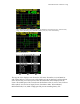
TKG250 Ultrasonic Thickness Gauge Example of Echo-to-Echo with blanking RF signal with cursor upside down “V” indicating where the measurement is being made The color waveform is also ideal to alert the operator of an alarm condition as such: Good readings in green Caution, % of high or low detected Tripped alarm in Red Large Thickness Reading (F3) 67
Extech Instruments Large Thickness F3= return to A-Scan Range-pre-set or Auto Zoom tracking to center echoes in the middle of the screen independent of test range thus allowing the operator not to fuss with the range control. Fixed ranges are Zoom, .5, 1, 2, 5, 10 and 20 inches or 12.7, 25.4, 125, 254 and 500 mm. To select the Auto Zoom tracking, use the left or right arrow key until range (bottom right is hightlighted) and then the up and down arrow keys to select the desired range.
TKG250 Ultrasonic Thickness Gauge Gain-Manual or Automatic, Gain can be adjusted automatically where the gauge will set the optimum range or manually, where the operator changes the range in 1dB steps. To select Auto, use the left or right arrow keys and highlight gain on the bottom right side of the display, use the up and down arrows to select Manual for desired setting or F2 for AGC. The Wave is defaulted to Auto gain where Automatic Gain Control (AGC) is on.
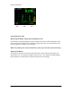
Extech Instruments The first Read line on the baseline is referred to as the Main Bang Blank while the second red line is referred to as the Blank After First Received echo. The white line represents the measured time interval between the two correct echoes. To adjust any of the above settings, from the main measurement screen, simply use the left, right, up or down arrow until the desired parameter is highlighted.
TKG250 Ultrasonic Thickness Gauge F1 F3 71
Extech Instruments 8 Technical Specifications Specifications for the TKG250 Ultrasonic Thickness Gauge with Live Color Waveform Size: 5" (127 mm) (L) x 3" (76.2 mm) (W) x 1.25" (31.75 mm) (H) Weight: 8 OZ (.23 kg) Thickness range: 0.008 - 20 inches (0.20 mm - 508 mm), depending on material, temperature and transducer selection Material velocity calibration range: 0.200-0.7362 in/μS (0.508-18.
TKG250 Ultrasonic Thickness Gauge Blanking: Main Bang Blank and Blank After First Received Echo Gain: Auto or Manual in 1 dB steps for varying test conditions Echo-to-Echo: used to ignore coatings and measure substrate only B-Scan: Cross sectional representation of test piece Measurement rate: 4/sec and 20/sec in fast mode Differential Mode: Displays the difference from the actual thickness measurement and a user entered reference value Alarms: Minimum/Maximum depth, vibralarm (vibration on alarm-patent pe
Extech Instruments 9 Software Options Echo-to-Echo The Echo-to-Echo feature should and can be used within the thickness range of the chart listed below. It is best to use the transducers designated with a –EE part number such as DK 537EE and DK 718EE. These transducers have greater damping allowing more stable readings in Echo-to-Echo mode. To calibrate in Echo-to-Echo, first press MENU OK, scroll to set up, press MENU OK and find where E to E is displayed.
TKG250 Ultrasonic Thickness Gauge readings up to the file size of 5,000 readings or what was pre-determined in the current file (See Datalogging) set up. Here is a picture of the B-Scan on a test block. Saving a B-Scan to memory.
Extech Instruments 10 Technical Assistance Contact Flir Systems for specific technical assistance or troubleshooting questions. See below: Calibration, Repair, and Customer Care Services FLIR Systems, Inc. offers repair and calibration services for the Extech Instruments products we sell. NIST certification for most products is also provided. Call the Customer Service Department for information on calibration services available for this product.
TKG250 Ultrasonic Thickness Gauge Calibrage, réparation et services après-vente FLIR Systems, Inc. offre des services de calibrage et de réparation pour les produits Extech Instruments que nous commercialisons. Nous fournissons également une certification NIST pour la plupart des produits. Contactez notre service client pour toute information sur les services de calibrage disponibles pour ce produit. Un calibrage doit être effectué chaque année pour vérifier les performances et la précision du mètre.
Extech Instruments Servicios de calibración, reparación y atención a clientes FLIR Systems, Inc., ofrece servicios de reparación y calibración para los productos que vendemos de Extech Instruments. Además ofrecemos certificación NIST para la mayoría de los productos. Llame al Departamento de Servicio al Cliente para solicitar información de calibración para este producto. Para verificar el funcionamiento y precisión se debe realizar la calibración anual.