USER GUIDE TKG100 Digital Ultrasonic Thickness Gauge TKG150 Digital Ultrasonic Thickness Gauge with Datalogger
Extech Instruments WARRANTY FLIR Systems, Inc. warrants this Extech Instruments brand device to be free of defects in parts and workmanship for two years from date of shipment (a six month limited warranty applies to sensors and cables). If it should become necessary to return the instrument for service during or beyond the warranty period, contact the Customer Service Department for authorization. Visit the website www.extech.com for contact information.
LIABILITY Ultrasonic testing is a function of using the proper equipment (electronics, transducer, cable and couplant combination) for the inspection and a qualified operator who knows how to use this manual, the instruments and all calibration procedures. The improper use of this equipment, along with the improper calibration can cause serious damage to components, factories, facilities, personal injury and even death.
Extech Instruments Table of Contents Table of Contents ........................................................................................ 4 1 Getting Started ......................................................................................... 7 About the TKG Series ............................................................................. 7 Probe Zero................................................................................................ 8 Keypad Functions ...........................
Automatic Zero ....................................................................................... 24 Measurement Mode with a Datalogger (TKG150) ....................... 26 Measurement Mode without a Datalogger (TKG100) .................. 27 4 Measurement Mode Setup Options ................................................. 29 Using the Clock ...................................................................................... 31 Setting LCD Contrast .....................................................
Extech Instruments Copying a File ........................................................................................ 71 Deleting a File ........................................................................................ 74 7 Technical Specifications ...................................................................... 76 8 Software Options ................................................................................... 79 B-Scan (TKG150 only) .................................................
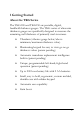
1 Getting Started About the TKG Series The TKG100 and TKG150 are portable, digital, handheld thickness gauges. The TKG series of ultrasonic thickness gauges are specifically designed to measure the remaining wall thickness of primarily steel structures.
Extech Instruments The TKG100 is a base gauge offering a simple user interface packaged in the same custom molded highdensity plastic case with rubber keypad as the other more sophisticated models. This gauge offers reliable, accurate thickness readings on mostly steel structures with access to only one side.
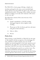
working in accordance with electronic zeroing procedures. This feature is particularly important on high temperature materials and when the transducer becomes worn. Important Notice: Please make sure the transducer is not coupled to the test piece when the gauge is first turned on and that there is no couplant on the end of the transducer. The transducer should also be at room temperature, clean without any noticeable wear.
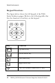
Extech Instruments Keypad Functions The figure below shows the full keypad of the TKG Series thickness gauges. Refer to the following table that lists the function of each key on the keypad. Key Function Up arrow key Down arrow key Left arrow key Right arrow key On/Off symbol (under the F1 key) 10 TKG100_TKG150 Ultrasonic Thickness Gauge User Guide v2.
MENU/OK key F1 key F2 key F3 key Function Keys Function keys, or F keys, such as F1, F2, and F3 have various gauge functions and may change depending on the display screen. View the bottom of the display screen for the function that corresponds with the appropriate F key. For example, F1 may correspond with the Save function, F2 with the Freeze function, or F3 with the Directory function (Dir). Display Screen The gauge has a graphic style Liquid Crystal Display (LCD).
Extech Instruments The TKG series is designed to show the parameters selected in the center of the display screen. F1 F2 F3 The top part of the display screen for TKG150 model shows the File name, ID number, AA, and 0001 for grid column and row. The lower part of the display acts as an interactive tool that allows you to decide how you want to proceed with the information that is displayed on the screen.
Battery Power Monitoring the Battery from the Display The TKG series constantly displays the percent battery life on the bottom right hand corner of the display screen. When the gauge gets below 20 %, the indicator will flash. Replacing the Batteries To replace the batteries, unscrew the battery door on the bottom of the gauge and slide out the two “AA” batteries. Replace with two new “AA” batteries paying attention that both positive ends are facing towards the top of the gauge.
Extech Instruments 2 Basic Gauge Operations Power on the Gauge To power on any of the TKG series thickness gauges follow these steps: 1. Press and hold the F1 key for more than 3 seconds. The power symbol is under the F1 key printed on the keypad as shown below. Power symbol under the F1 key 14 2. The following (or similar) will appear on the display screen of the thickness gauge: 3.
4. Use the up and down arrow keys to select a transducer and press OK key. (Please note that the transducer selection will automatically display the transducer last used prior to shut off. 5. Press F1 to select the Setup option. 6. Press F2 to select the Reset option. 7. Press F3 to select the Bklite option.
Extech Instruments Performing a Reset (TKG100) You can reset the TKG100 gauge settings back to the default settings by performing a gauge reset. Note: Performing a reset permanently deletes all of the saved parameters from the gauge and replaces the settings with default values. To perform a reset, follow these steps: 16 1. From the Home screen (transducer select screen), press the F2 Reset key. The following Reset screen appears: 2. Press the OK button and the ARE YOU SURE? Prompt will appear.
Performing a Reset (TKG150) You can reset both the TKG150 DATABASE and PARAMETER settings back to their default settings in one gauge reset or you can reset the PARAMETER and DATABASE data individually. Note: Performing a reset permanently deletes all of the saved parameters from the gauge and replaces the settings with default values. To perform a reset, follow these steps: 1. From the Home screen (transducer select screen), press the F2 Reset key. The following Reset screen appears: 2.
Extech Instruments 4. Note that performing a Database Reset clears all the files in the database and keeps the first three: Linear, Row increment and Col increment database files with cleared readings. All the user created files in the database will be cleared and deleted. 5. After performing a Reset, the Home screen appears automatically. Backlight The backlight can be turned On or Off by pressing F3 – Bklite.
About Screen You can find information about any of the TKG series thickness gauges such as the model number, version number and contact information from the gauge‟s About screen. To go to the About Screen, follow these steps: 1. From the Home screen (transducer select screen), press the F2 – Reset key. The Reset screen will appear. 2. Press the F3 – About key. The following About screen appears. 3. Press the F1 – Exit key to return to the Reset selection screen.
Extech Instruments 3 Calibrating the Gauge Calibrating is the process of adjusting the gauge for a specific material and transducer before testing material to make sure that all measurements are accurate. You must always calibrate before measuring material for standard accuracy. To measure a thickness of unknown material you need to know the velocity of the sound in the unknown material.
exit the calibration screen without performing any calibration, press OK. To proceed to the Velocity calibration, follow the following instructions. Cal screen for TKG100 non-datalogger version While measuring the thicker step, select VEL by pressing F3. After selecting VEL, you can take the transducer off the test block. If the displayed measurement is different than the known value of the step, use the up or down arrow key to adjust the displayed value to the known value of the step.
Extech Instruments To calibrate both: velocity and zero at the same time first go to the Calibration mode as shown in Velocity Calibration Only section. While measuring the thicker step, select VEL by pressing F3. After selecting VEL you can take the transducer off the test block. If the displayed value is different than the known value of the step, adjust the value by pressing up or down arrow keys and press F1/CAL. Then while measuring the thinner step select ZERO by pressing F2.
and electronics. This is called delay line and zero calibrated value for the transducer. To perform a zero calibration, go to the Cal mode as shown in Velocity Calibration Only section. Then while measuring the thinner step, select ZERO by pressing F2. After selecting ZERO, you can take the transducer off the test block. If the displayed measurement is different than the known value of the step, use the up or down arrow key to adjust the displayed value to the known value of the step.
Extech Instruments the sensitivity of the transducer is too low and whether the transducer should be replaced. Automatic Zero To perform an Automatic Zero or Auto Zero, you must first select a transducer option from the Transducer selection screen and press the Menu/OK key. To continue the Auto Zero, follow these steps: 1. 24 Follow the instructions given on each display screen; the first of which will prompt you to wipe off any couplant from the transducer and wait three seconds.
2. After three seconds the gauge automatically begins to zero the transducer. During the delay line calibration a screen appears displaying the message “Performing Auto Zero”. 3. A warning message will appear on the display screen if the delay line is below the acceptable limit for accurate thickness measurements. You will need to replace the transducer or select the F1 key to acknowledge the warning message and continue using the same transducer, which may have a worn surface. 4.
Extech Instruments 4 Measurement Mode Measurement Mode with a Datalogger (TKG150) For the TKG150 series datalogger the display screen in Measurement mode will look similar to the screen below: To continue in Measurement mode, follow these steps: 26 1. Press the F1 key to select the Save T option. (See: Save section.) 2. Press the F2 key to select the Freeze option. (See: Freeze section.) 3. Press the F3 key to select the Dir (Directory) option. (See: Directory section.) 4.
Measurement Mode without a Datalogger (TKG100) The TKG100 display screen in Measurement mode will look like the screen below: To continue in Measurement mode, follow these steps: 1. Press the F1 key to select the Alarm option. (See: Alarm section.) 2. Press the F2 key to select the Freeze option. (See: Freeze section.) 3. Press the F3 key to control the display backlight. (See: Display Backlight) 4. Press the Menu / OK key to select the Menu option. (See: Menu section.
Extech Instruments Also, the file symbol, filename, ID: xx,xxxx are not displayed in the TKG100 series thickness gauge. 28 TKG100_TKG150 Ultrasonic Thickness Gauge User Guide v2.
Measurement Mode Setup Options The following modes are available (please note that in the TKG100 model the Datalogger mode is not available): To select the Measurements setup mode, first access the main MENU (using the MENU/OK button from the Home screen), and then follow these steps: 1. Use the arrow buttons to highlight MEASUREMENTS and then press Menu OK. A screen similar to the one below will appear (a full list of setup options is shown later in this section): 2.
Extech Instruments mode”. To do this, simply use the left and right key (indicated in the top right hand of the display screen) to change the setting of the highlighted parameter. 3. The entire list of available MEAUREMENT MODE parameters for the TKG100 and TKG150 (red items TKG150 only) are as follows: FAST GAIN HOLD MEAS, TYPE VEL XDUCER ALARM BSCAN DIFF E-TO-E 30 OFF LOW dB OFF THICKNESS 0.23596 IN/US DKS537 5.0MHz OFF OFF OFF OFF TKG100_TKG150 Ultrasonic Thickness Gauge User Guide v2.
Setting the Clock The TKG series thickness gauges have an internal realtime clock that includes the year, month, day and time. This option appears under the Initial Settings option. The entire list of available clock setup options are as follows: TIME FORMAT DATE FORMAT MINUTE HOUR DAY MONTH YEAR 12 HR MM/DD 21 01 PM 01 01 2013 To set the time and date, follow these steps: 1. Select CLOCK from the INITIAL SETTINGS list in the main MENU.
Extech Instruments previous setup. 32 2. To change the Time Format, select TIME FORMAT using up/down arrow keys. Use the left/right arrow keys to select between 12 HR and 24 HR options. 3. To change the Date Format, select DATE FORMAT using up/down arrow keys. Use the left/right arrow keys to select between MM/DD and DD/MM options. 4. To set Minute, select the MINUTE option using up/down arrow keys. Use left/right arrow keys to decrease/increase the minute value.
6. To set Day, select the DAY option using up/down arrow keys. Use left/right arrow keys to decrease/increase the day value. You can set the day value from 01 to 31. 7. To set Month, select the MONTH option using up/down arrow keys. Use left/right arrow keys to select a Month from JAN to DEC. 8. To set Year, select the YEAR option using the up/down arrow keys. Use left/right arrow keys to select the year value from 2005 to 2025.
Extech Instruments Not enough couplant Surface is too rough or rusty Low Transducer sensitivity Temperature is too high Dis-bond exists between the coating and the steel In the event you try to save a reading in LOS with the TKG150, the Notes screen will automatically appear so that a reason is given for saving an LOS. You can scroll to the appropriate note and press the soft Save key.
Using the Fast Option The Fast option is available by accessing the main MENU, selecting MEASUREMENTS, and then selecting FAST from the list. To select the Fast option, follow these steps: 1. Use the up and down arrow keys to highlight the Fast option and press the OK key. 2. The following parameters are available: 3. Use the up and down arrow keys to select the desired parameter and press the OK key. 4. Press F1 Back key to return to the Measurement mode.
Extech Instruments In the Measurement the selected Fast option setting is displayed similar to the screen below: Helpful Hint: When using the FASTMIN mode, if you press the F2 key “Freeze” prior to LOS, the gauge will display the last minimum prior to the LOS so that the actual couplant on the end of the transducer is not registered as a legitimate minimum reading.
value. If you select the On parameter from the Fast option, the LOS will work normally and not show the measured reading. The screens below reflect different parameters selected from the Fast option. For example, the top screen shows the FASTMAX with LAST MAX measurement on LOS, and the bottom screen shows the FASTMIN with LAST MIN measurement on LOS. Note: The LOS flag indicates the LAST MAX or the LAST MIN value and is shown based on the FastMax or FastMin setting.
Extech Instruments To reset the tracking of LAST MAX and LAST MIN measured value press the OK (Menu) key. Using the Gain Option (TKG150 only) Gain refers to an increase in signal power (echo height) and is typically measured in decibels (dBs). The Gain function is useful for setting a reference level where by making it easier to add or subtract gain. There are three Gain options, which include: LOW dB, STD dB & HI dB. The Gain selection is available from the Measurements mode screen in the Main MENU. 1.
In the Measure mode screen the Gain option that you select is displayed on the center/right side of the display. Using the Diff Option There are 3 Diff options: ABSOLUTE: Absolute, where the gauge will display a thickness value as an absolute number. For example, diff abs = 0.500” and the real thickness is 1.000 inch, the display will show diff abs 0.500. If the real value is 0.300, the gauge will display, -0.
Extech Instruments 5 Alarm Options Using the Alarm Option The TKG series thickness gauges offers various alarm settings to alert you of low or high thresholds via audible sounds, display flashes, vibrations (if on) and illuminating keypad. There are several alarms options, which include: 40 Alarm On/Off: Sets the audible alarm either on or off. Low Alarm: Audible alarm will occur and display will flash when the displayed reading is less than the low alarm reference value.
displayed reading is higher than the high alarm reference value. High_Low Alarm/Vibra (TKG150 only): Audible alarm will occur and display will flash as well as vibrate when the displayed reading is less than the low alarm or greater than the High alarm reference value. The Alarm option is available from the Measurements screen list. 1.
Extech Instruments the previous page. 2. Use the up and down arrow keys to select the desired alarm type and then press the OK key. The following screen below appears (screens will differ slightly based on alarm type selection). Use the up and down arrow keys to select the high, low, or percent parameters and then use the left/right arrow keys to change the Alarm limits. Press the OK key to continue. Note: The Low Alarm limit will not go beyond the High Alarm limit. 3.
Visual and Audible Alarm The Visual Alarm conditions can be viewed from either a red, yellow or green LED that light up under the F1, F2, or F3 keys on the keypad. As an example, when using the 5 step English test block with thicknesses of 0.100, 0.200, 0.300, 0.400 and 0.500 inches, if you enter alarm high-low you will first need to enter the high value. Enter 0.500 and press enter. Next you will need to enter the low value of 0.100 in. The display will ask you to enter the percent reading of the high low.
Extech Instruments The Audible Alarm turns the beeper on the gauge either on or off based on the same alarm conditions used for visual alarm stated above. ‘Vibra’ Alarm (TKG150 only) The gauge will physically vibrate when the Vibrating Alarm is active based on the same alarm condition used for visual alarm. The Vibrating Alarm, noted as ( ( . ) ) on the gauge display, can be enabled with varying alarms and alarm conditions as shown on the screens below: Visual and Audible Alarm is enabled.
Visual, Audible, and Vibrating alarm enabled .)) symbol appears next to the alarm icon. The letter H (High) appears in the alarm icon Alarm condition has occurred meaning the measured reading is greater than the High Alarm limit. The letter H (High) appears in the alarm icon. The screen above has the Vibrating alarm enabled as the .)) symbol appears next to the alarm icon.
Extech Instruments Visual, Audible, and Vibrating alarm enabled .)) symbol appears next to the alarm icon. The letter L (Low) appears in the alarm icon Alarm condition has occurred meaning the measurement reading is less than the Low Alarm limit. The letter L (Low) appears in the alarm icon. The screen above has the Vibrating alarm enabled as the .)) symbol appears next to the alarm icon.
6 Using the Echo-to-Echo Option (TKG150 only) The Echo-to-Echo option allows you to make measurements between two consecutive back-wall echoes. Therefore, a good usage of the Echo-to-Echo option is for measuring through coatings to measure only the true metal thickness.
Extech Instruments 7 Special Gauge Functions The TKG series thickness gauges have many special functions that go beyond the basics, mainly in the TKG150 model. This section will discuss these special gauge functions in detail. Using the Save Option (TKG150 only) You are able to save your data via the Save option. To use the Save option, follow these steps: 1. From the Measurement mode screen, press [F1] (Save T). The data saved will depend on your setup parameters.
2. If the Notes option is set to Always then the thickness reading is stored at the ID location [Linear], [Row], [Col] with notes. To change the Notes settings, select the Notes option from the Datalogger screen in the MAIN Menu.
Extech Instruments Using the Freeze Option You can freeze your data via the Freeze option. To use the Freeze option, follow these steps: 1. From the Measurement mode screen, press [F2] (Freeze). The following screen comes up after pressing [F2] (Freeze) whereby showing the flag “Freeze” under the thickness reading. You are now in Freeze mode. The [F2] selection also changes from Freeze to Unfreeze. 50 TKG100_TKG150 Ultrasonic Thickness Gauge User Guide v2.
TKG150 Datalogger version TKG100 Non-datalogger version 2. Press [F1] (Save) to save the reading. (See Using the Save Option for more information.) 3. Press [F2] (Unfreeze) to disable the Freeze mode 4. Press [F3] (Dir) to perform file operations. (See Using the Directory Option for more information.) 5. While in Freeze mode the menu options are disabled. The display will prompt you to unfreeze the gauge.
Extech Instruments TKG150 Datalogger version TKG100 Non-datalogger version 52 TKG100_TKG150 Ultrasonic Thickness Gauge User Guide v2.
Using the Menu Option For the TKG100 and TKG150 models you can operate in Measure mode. To use the Measure mode, follow these steps: 1. Press the Menu (OK) key to select the Menu options from Measure mode.
Extech Instruments The following Menu options are available: TKG150 Datalogger version TKG100 Non-datalogger version 54 TKG100_TKG150 Ultrasonic Thickness Gauge User Guide v2.
8 Using Datalogger Directory Mode (TKG150 only) Note: This section applies only to the TKG150 Thickness Gauge with a datalogger. If you do not have a datalogger, you may skip this section. To use the datalogger Directory mode, follow these steps: 1. From the Measurement mode screen press [F3] (Dir) to select the Directory mode. By pressing [F3] (Dir) you will be able to review, create, delete, select, rename and clear stored thickness and copy. 2.
Extech Instruments 56 3. Press the OK key to select a file in the directory view. 4. To create a custom file see Creating Custom Files section. 5. To review thickness readings, see Reviewing a File section. 6. To rename custom file, see Renaming a File section. 7. To clear an entire file, see Clearing a File section. 8. To clear selected readings from a file, see Reviewing a File section. TKG100_TKG150 Ultrasonic Thickness Gauge User Guide v2.
9. To create copy of the existing file structures, see Copying a File section. 10. To delete a custom file, see Deleting a File section. The first three files cannot be deleted or renamed. These files are factory default files available for you to start storing thickness reading or make a quick copy of the file structure (Linear or Grid [Col, Row]) in order to start saving data in the new file. (See File System for more information.
Extech Instruments Managing the Datalogger File System The TKG150 supports the following two files types: Linear file: Consists of ID# from 0001 to 5000. The extended memory option consists of ID# from 1 to 500000. Grid file: Consists of ID# as COLUMN and ROW. The COLUMN is single or double digit capital alpha character from A to Z and AA to ZZ. The ROW is a four digit number based on the 5000 / COLUMN.
A,1 B,1 : Z,1 AA,1 AB,1 : AF,1 to to A,156 then B,156 then to Z,156 then to AA,156 then to AB,156 then to AF,156 If a new GRID file with END COLUMN = ZZ, then the maximum ROW you can slew up to is limited to 5000/(26 for A to Z + 26*26 for AA to ZZ) = 7.
Extech Instruments Note that there are two different types of Grid files: ROWINC and COLINC. The above two examples show how the ID locations are incremented in ROWINC type file only. Here the Row value is incremented first, while updating ID location. Whereas, in a COLINC type file, Column value is incremented first. So for a COLINC file with END COLUMN value AF, the ID locations will increment as follows: A,1 to AF,1 then A,2 to AF,2 then . .
Creating Custom Files To create a custom file in the datalogger, follow these steps: 1. Press [F3] (Dir) from the Measurement mode screen. The following screen appears: 2. Use the up and down arrow keys to highlight the next Empty file in the list.
Extech Instruments 62 3. Press the OK key and select RENAME, the following screen appears: 4. Use the up, down, left, and right arrow keys to select the characters of the filename. Press the OK key to accept the selected characters. If you make an error, press [F2] (Del) to delete the last character of the entered filename. 5. Press [F3] (Done) when you are finished entering the filename. The following screen appears: 6. Use the left and right arrow keys to select a file type.
Selecting a Custom Linear File When you select a LINEAR file format you are prompted to select START and END file points. With the extended memory, you can store up to 100,000 readings allowing you more total files. Pressing the F3 (Done) key again will take you to the Measure mode displaying the new filename in the top left corner and the next ID location in the top right corner. Selecting a Custom Grid File When you select a grid file type, the display changes as shown below.
Extech Instruments Use the up and down arrow keys to select the END ROW option. Now press left or right arrow key to change the END ROW value. Then press down arrow key to select END COL option. Press left or right arrow key to change the END COL value. Since the file size is limited to 5000, the END COL value is limited to 5000/END ROW. Note that the „FILE SIZE‟ will change depending on the END ROW and END COL settings. When you are finished selecting END ROW and END COL values, press F3 (Done).
Reviewing a File To review a file from the Measurement mode screen in datalogger version only, follow these steps: 1. Press [F3] (Dir) from the Measurement mode screen. The following screen appears: 2. Select the file you would like to review using the up and down arrow keys and press the OK key.
Extech Instruments ABCD CLEAR ALL READI NGS COPY DELETE FI LE RENAME REVI EWDETAI LS REVI EWGRI D EXI T The three factory default files have only 3 options: Clear All Readings, Copy, and Review Details. Custom files have 5 options: Clear all readings, Copy, Delete file, Rename, Review details, and Review Grid. Select the Review option and press the OK key to review the file. Reviewing a Linear File The linear file shows the ID# and the stored readings along with the units.
F2 (Clear). Note that once a reading is cleared, it cannot be restored. To store another reading in the file location that has been emptied by the Clear operation, highlight that location by pressing up or down arrow key. Then press OK to go to the measure mode. When you have the new reading to be stored in the emptied file location, press F1 (Save). The new reading will be saved in that location and the display will show the next empty file location in the top right corner.
Extech Instruments The following screen appears: 2. Use the up and down arrow keys to select the file you would like to rename and press the OK key. Note: The Rename option is not available for the first three factory default files. 3. 68 Use the up and down arrow keys to select the Rename option and press the OK key to rename the file. A screen the same or similar to the one below appears. TKG100_TKG150 Ultrasonic Thickness Gauge User Guide v2.
4. Use the up, down, left, and right arrow keys to select the characters of the filename. Press the OK key to accept the selected characters. If you make an error, press [F2] (Del) to delete the last character of the entered filename. 5. Press [F3] (Done) when you are finished entering the filename. The old filename will be updated with the new filename in the directory as shown in the example below. Note: Press [F1] (Exit) to exit the screen without renaming the file.
Extech Instruments Clearing a File To clear (or delete) a single thickness reading at a time from a file, see Reviewing a File section. To clear all the readings from a file, use the clear file option. To do this, from measurement mode, press [F3] (Dir) for the Directory mode. The following screen appears: 70 1. Use the up and down arrow keys to select the file you want to clear and press the OK key. 2.
YES/NO/EXIT confirmation: Press [F1] (Exit) to exit without clearing the thickness readings. Press [F2] (Yes) to clear the stored thickness from the entire file. Press [F3] (No) to exit without clearing the thickness readings. If the file is already clear, the unit will show „NO READINGS TO CLEAR.‟ message. Copying a File To copy a file, from the Measurement mode screen in datalogger version only, follow these steps: 1. Press [F3] (Dir) for the Directory mode.
Extech Instruments The following screen appears: 2. Use the up and down arrow keys to select a file and press the OK key. Any file structure (factory default or custom) can be copied. Note: When you copy a file only the structure of the file ID# is copied and not the associated file readings. 3. 72 Use the up and down arrow keys to select the Copy option and press the OK key. The following confirmation prompt or a similar prompt appears with the next Empty file highlighted as the default choice.
Press up or down to select an Empty file and press OK to assign it a new filename. The following screen appears. 4. Use the up, down, left, right arrow keys to select the characters of the filename and press the OK key to accept the selected characters. If you make an error, press [F2] (Del) to erase last character before the cursor. 5. Press [F1] (Exit) to exit without copying the file. 6. Press [F3] (Done) when you are finished entering the filename.
Extech Instruments Deleting a File To delete a file, from the Measurement mode screen in the datalogger version only, follow these steps: 1. Press [F3] (Dir) for the Directory mode. The following screen appears: 2. Use the up and down arrow keys to select the file to be deleted and press the OK key. Note: Only custom files can be deleted. The factory default files cannot be deleted. 3. 74 Use the up and down arrow keys to select the Delete File option and press the OK key.
confirmation prompt for YES/NO/EXIT appears. Press [F1] (Exit) to exit the screen without deleting the file. Press [F3] (No) to exit the screen without deleting the file. Press [F2] (Yes) to delete the file and remove the file from the directory.
Extech Instruments 7 Technical Specifications Specifications for the TKG100/TKG150 Ultrasonic Thickness Gauges Size: 5" (127 mm) (L) x 3" (76.2 mm) (W) x 1.25" (31.75 mm) (H) Weight: 8 OZ (.23 kg) Thickness range: 0.008 - 20 inches (0.20 mm - 508 mm), depending on material, temperature and transducer selection Material velocity calibration range: 0.200-0.7362 in/μS (0.508-18.
Differential Mode: Displays the difference from the actual thickness measurement and a user entered reference value Alarms: Minimum/Maximum depth, vibralarm, audible/visual indications as well as keypad illumination Illuminating keypad: F1 = Red, F2 = Yellow and F3 = Green for easy, go/no-go testing (Patent Pending) Automatic probe wear indicator ( Transducer attendant): Automatically informs the operator to replace the transducer (Patent Pending) Ergonomics: User selectable left-handed or right-handed disp
Extech Instruments Specification differences for TKG100 and TKG150 Models Item Thickness range Delay line zero measurement Scan mode Specification 0.008-0.20 inches (20mm-508mm) Auto at power up with listed numeric value.
8 Software Options Echo-to-Echo (TKG150 only) The Echo-to-Echo feature should and can be used within the thickness range of the chart listed below. To calibrate in Echo-to-Echo, first press MENU OK, scroll to set up, press MENU OK and find where E to E is displayed. Use the right arrow to turn ON or press MENU OK and scroll to ON. You will see a symbol in the top right looking like Echo-to-Echo.
Extech Instruments B-Scan (TKG150 only) The B-Scan represents a cross sectional view on the test piece. The simplest example is to show a 5 step test block. To turn on the B-Scan on the TKG150, press MENU/OK, scroll to MEASUREMENTS and press OK, select B-scan and press MENU/OK. First enter the maximum thickness you expect to scan using the up, down, left and right keys, then turn on the B-Scan scrolling down and right arrow (left arrow for off). Press F3 in lefty or F1 in righty mode when done.
9 Technical Assistance Call Extech Instruments for specific technical assistance or troubleshooting questions. See the customer care information on the following pages or visit the website www.Extech.com Calibration, Repair, and Customer Care Services FLIR Systems, Inc. offers repair and calibration services for the Extech Instruments products we sell. NIST certification for most products is also provided.
Extech Instruments Calibrage, réparation et services après-vente FLIR Systems, Inc. offre des services de calibrage et de réparation pour les produits Extech Instruments que nous commercialisons. Nous fournissons également une certification NIST pour la plupart des produits. Contactez notre service client pour toute information sur les services de calibrage disponibles pour ce produit. Un calibrage doit être effectué chaque année pour vérifier les performances et la précision du mètre.
Servicios de calibración, reparación y atención a clientes FLIR Systems, Inc., ofrece servicios de reparación y calibración para los productos que vendemos de Extech Instruments. Además ofrecemos certificación NIST para la mayoría de los productos. Llame al Departamento de Servicio al Cliente para solicitar información de calibración para este producto. Para verificar el funcionamiento y precisión se debe realizar la calibración anual.
Extech Instruments 84 TKG100_TKG150 Ultrasonic Thickness Gauge User Guide v2.