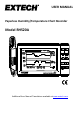
USER MANUAL Paperless Humidity/Temperature Chart Recorder Model RH520A Additional User Manual Translations available at www.extech.
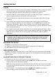
Introduction Congratulations on your purchase of the Extech RH520A Temperature + Humidity Chart Recorder. The RH520A measures and displays Temperature, Humidity, and Dew Point. The remote (detachable) probe senses the ambient conditions while the LCD display graphs and provides numerical representation of the readings. Programmable audio-visual alarms alert the user when ambient conditions reach alarm presets. The optional alarm module permits automatic relay switching when alarm presets are reached.
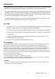
RH520A Description 1. 2. 3. 4. 5. 6. 7. 8. 9. 10. 11. 12. 13. 14. 15. Remote sensor Sensor cable LCD Display Swivel keypad / table-top stand PC interface jack Universal alarm module jack AC adaptor jack DATA RESET button (clears recorded measurement data and alarm history) Temperature units select switch (C or F) PROGRAMMING RESET button (clears programming changes but retains measurement data and alarm history) Display CONTRAST adjust Sensor cable storage area ‘AA’ 1.
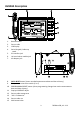
DISPLAY DESCRIPTION 1. Temperature measurement graph 2. Internal memory usage meter 3. Vertical axis scale limits 4. Cursor / Alarm indicators 5. Push-button lock-out status indicator 6. Time display 7. Relative Humidity (RH) measurement graph 8. Date display 9. Function indicators 10. Numerical temperature reading display 11. Numerical RH reading display 12. Battery status indicator 4 RH520A-en-GB_v4.
PUSH-BUTTON DESCRIPTION VIEW Return the LCD to the Standard View Escape from any setting function without storing value changes Scrolls highest and lowest (MAX/MIN) readings when in Standard View ALARM Display or Set alarm values TIME Display a reading stored at specific Time and Date Set and Display the recording Sampling Rate Set the Time and Date SET Used in combination with other buttons to set new parameter values Stores new parameter values and returns to the Standard View TEMP Used in combin
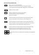
KEYPAD QUICK REFERENCE (ALSO SHOWN ON REAR OF THE RH520A HOUSING) Key-press VIEW Function Selects view mode TIME + VIEW View Sample Rate Second / Alternate Keystrokes VIEW modes: Normal, TEMPmax, RHmax, TEMPmin, RHmin VIEW to cancel, exit mode Movers cursor through stored points Arrow keys to select, VIEW to exit VIEW to exit ALARM selects next Alarm, VIEW to exit ALARM selects HIGH/LOW, SET to save ALARM selects HIGH/LOW, SET to save VIEW to exit SET ARROW KEYS Saves new settings Scroll through selec
Getting Started POWER 1. The RH520A runs on battery power or AC adaptor (5VDC 500mA). Battery power consists of three (3) ‘AA’ batteries. See the Battery Replacement section of this manual when changing/installing the batteries. Note: Batteries and adaptor are supplied. 2. Plug the AC adaptor in the AC adaptor jack shown in the Description section. The batteries will act as battery back-up in the event of an AC power failure. 3.
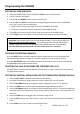
Programming the RH520A SETTING THE TIME AND DATE 1. From the Standard View, press the SET and TIME buttons simultaneously 2. The SET indicator will appear 3. Use the UP and DOWN arrow buttons to set the time 4. Use the LEFT and RIGHT arrow buttons to step through the minutes, hours, AM/PM/24Hour, day, month, and year parameters If AM or PM is selected, the date format will be MONTH-DAY-YEAR If 24-hour is selected, the date format will be DAY-MONTH-YEAR 5.
SETTING THE VERTICAL RESOLUTION FOR THE RH GRAPHIC DISPLAY 1. Press the SET, RH, and UP arrow buttons simultaneously 2. The upper RH range indicator will flash, and the SET icon will appear 3. Use the UP-DOWN buttons to change the upper RH value in 10% increments 4. Press the RH button and the lower RH range indicator will flash 5. Use the UP-DOWN buttons to change the lower RH value in 10% increments 6. Note that the upper and lower RH values cannot overlap 7.
9. Press VIEW at any time to return to the Standard View without saving the changes SETTING THE RH ALARM LIMITS 1. Press the SET, RH, and ALARM buttons simultaneously from the Standard View 2. The ALARM, SET, and MAX indicators will switch on. All of the TEMP indicators will switch off 3. Use the UP-DOWN arrow buttons to increment/decrement the HIGH RH alarm limit. Use the LEFT-RIGHT arrow buttons to step through the decades 4. Press the ALARM button. The MIN (low alarm) indicator will switch on 5.
Display Modes STANDARD VIEW The Standard View is the display state of the RH520A when it is turned on. Refer to the diagram in the display description section of this manual for a representation of the Standard View. To reach the Standard View at any time, press the VIEW button. Note that the display automatically reverts to the Standard View five (5) minutes after the last button press. CURSOR The CURSOR location is indicated by a small diamond located between the two graphs. See diagram.
MAX-MIN DISPLAYS 1. Press the VIEW button in the Standard View to display the highest (MAX) and lowest (MIN) temperature and RH readings from all the stored measurement records. 2. When viewing the highest readings, the MAX indicator will switch on. When viewing the lowest readings, the MIN icon will switch on. 3. The cursor will move to the location of the MIN or MAX reading within the graph.
USING THE CLOCK TO SORT THROUGH STORED READINGS 1. Press the TIME button in the Standard View mode 2. Use the ARROW buttons to select the time of day. 3. The temperature and humidity readings for the selected Time will display. 4. Press VIEW to return to the Standard View. DEW POINT DISPLAY Press the TEMP and the RH buttons simultaneously to view the Dew Point reading. The DEW POINT display icon will switch on above the temperature. See the diagram below. Press VIEW to return to the standard view mode.
SAMPLE RATE DISPLAY 1. Press the VIEW and the TIME buttons simultaneously from the Standard View mode 2. Both numerical displays will switch off so that the LCD can show only the sample rate in minutes (the MIN display icon will switch on) 3. The projected TIME-DAYS that the internal memory will be full (based on the current sample rate) is displayed in the TIME and DATE display areas 4. To change the sample rate, refer to the programming section of this manual. 5.
Alarm Conditions and the Alarm History When in Standard View mode: If the ALARM display icon is flashing – an Alarm condition currently exists. If the ALARM display icon is ON steady – there are past Alarms to view in the Alarm history. Use the ALARM button to view the Alarm history as described elsewhere in this manual. If an Alarm is tripped, press the ALARM button to silence it. Press and hold the SET button for 2 seconds to clear an alarm through the external relay module.
Specifications Display Graphical LCD Temperature Range/Accuracy Humidity Range/Accuracy -17 to 50oC (0.0 to 120.0oF) / ±1.0oC (1.8oF) -28 to -17oC (-20.0 to 0oF) / 3oC (±5.4oF) 50 to 60oC (120.0 to 140oF) / 3oC (±5.4oF) 10 to 95%/±3.0% RH Dew point temperature -28 to 60oC (-20.0 to 140.0oF) Internal memory storage 49,152 complete reading sets Sampling interval Selectable recording rate: 0.1(6 seconds) to 199.