User Manual Current / Voltage Calibrator Model PRC15 Additional User Manual Translations available at www.extech.
Introduction Thank you for selecting the Extech Model PRC15. This device is shipped fully tested and calibrated and, with proper use, will provide years of reliable service. Please visit the Extech Instruments website (www.extech.com) to check for the latest version of this User Guide. Extech Instruments is an ISO-9001 certified company. Safety International Safety Symbols This symbol, adjacent to another symbol or terminal, indicates the user must refer to the manual for further information.
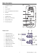
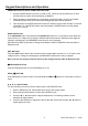
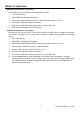
Meter Description 1. AC adaptor input jack 2. Display 3. Power ON/OFF 4. Source output adjustment arrow buttons 5. Set button 6. Unit button (mA or %) 7. I/O MODE button 8. MEM (memory STEP button) 9. Backlight/ZERO button 10. Test lead input jacks Display Layout 1. SOURCE mode icon 2. ZERO function status icon 3. MEASURE mode icon 4. Auto Power OFF active icon 5. Battery status icon 6. Measure mode value 7. Measure mode unit icon 8. Datalogger memory location 9.
Keypad Descriptions and Operation POWER BUTTON and AUTO POWER OFF FEATURE 1. Use the POWER button to turn the unit ON or OFF. When the unit is powered up, a short self-test will ensue after which the display will stabilize. 2. When the battery symbol flashes on the display, replace the battery as soon as possible. Low battery power may cause inaccurate readings and erratic meter operation. 3. This instrument is equipped with Auto Power OFF which turns the meter off after 10 minutes of inactivity.
SET BUTTON The SET button is used to manually step through the 5 stored output values. 1. While in Measure mode, select either the current or the voltage mode. 2. Short press the Mode button to Select the SOURCE mode. 3. Press the SET button and the value stored in memory location 01 will be sourced. “MEM.01” appears in the display. 4. Each press of the SET button will step through the 5 memory locations. 5. The arrow buttons can be used to adjust the value in each memory location.
Modes of Operation MEASURE (Input) Mode of Operation In this mode, the unit will measure up to 50mADC or 20VDC. 1. Turn the meter ON. 2. “MEASURE” will appear in the display. 3. Press and Hold the MODE button for >2 seconds to select mA or % or mV 4. Connect the Calibration Cable to the meter. 5. Connect the Calibration Cable to the device or circuit under test. 6. Read the measurement on the LCD display.
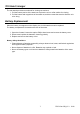
Tilt Stand / Hanger The rear stand provides two methods for viewing convenience. 1. Pull the bottom portion of the stand out to place the unit on a flat surface for viewing. 2. Pull the bottom and top portions of the stand out, and then rotate the stand to allow the unit to be hung. Battery Replacement When the battery icon appears on the display, the six AA batteries must be replaced. The battery compartment is located on the rear of the meter. 1.
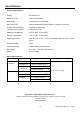
Specifications General Specifications Display Dot matrix LCD Maximum Load 1000 ohms @ 24mA Meter Power 6 AA batteries or AC adaptor Auto Power OFF Meter automatically powers off after 10 minutes of inactivity Current output capability 24mADC at 1000 ohms Voltage input impedance 10kohms minimum Operating Temperature 41ºF to 104ºF (5ºC to 40ºC) Storage Temperature - 4oF to 140oF (5ºC to 40ºC) Operating Humidity Max 80% up to 87ºF (31ºC) decreasing linearly to 50% at 104ºF (40ºC) Storage Humi