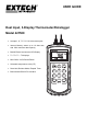
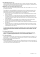
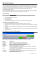
USER GUIDE Dual Input, 3-Display Thermometer/Datalogger Model 421509 Accepts J, K, T, E, R, S, & N thermocouples Internal Memory stores up to 16 data sets, with 1024 maximum data capacity Backlit Electro-luminescent LCD Display T1 / T2 / T1 – T2 displays 421509 APO ¡F T1 K MIN / MAX / AVG Record/Recall Selectable temperature units (C/F) Data Hold, Relative Mode, Elapsed Timer Bi-directional RS-232 PC Interface T1 ESC - ¡F T1-T2 0 ENTER ¡C/¡F [Limits] [INVT] 1 SAVE RE
Introduction Congratulations on your purchase of Extech’s Dual Input, 3-Display, Hand-Held Digital Thermometer/Datalogger. This portable digital thermometer is designed to use external K / J / T / E / R / S / N type thermocouples (K-type supplied). Temperature indication follows Reference Temperature/Voltage Tables (N.I.S.T. Monograph 175 Revised to ITS-90). It features an adjustable T/C offset and an RS-232 interface for uploading data to a PC using optional software and cable.
Specifications General Specifications Display Input Protection Reading rate 4-1/2 digit (19,999), 3-Display, LCD with EL Backlighting 24VDC or 24VAC rms maximum input on any combination of inputs. Max voltage between T1 and T2 inputs is 1V 2.5 times per second Input connectors Alarm Output Operating conditions Storage conditions Dimensions / Weight Power Supply Accepts standard sub-miniature thermocouple connectors 6-pin mini DIN, max.
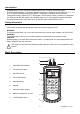
Operation There are three operation modes—Normal, Shift, and Setup mode Normal Mode This is the default mode. The operating functions for normal mode are printed on the face of each button in white. The following functions can only be used in Normal Mode. Power Button The Power key turns the thermometer ON or OFF. When entering data in Setup Mode, the power off function is disabled. [Limits] Button The Limits function will alert the user when a measurement exceeds a specified limit.
HOLD Mode (Main Display only) Press the HOLD button to enter the Data Hold mode, the "HOLD" annunciator will display. When HOLD is selected, the thermometer freezes the reading on the main display only. Press the HOLD button again to return to the normal measurement mode.
Shift Mode The operating functions for the shift mode are printed in yellow on the buttons. When in normal mode, push the SHIFT button to switch to shift mode. The word “Shift” will be displayed in the lower right corner of the LCD. To switch back to normal mode, press the SHIFT button again. °C/°F Key Readings can be displayed in degrees Celsius (°C) or degrees Fahrenheit (°F). Note that the meter remembers the unit of measure when it is turned off. Press the °C/°F key to change the temperature units.
Setup Mode The operating functions for the setup mode are printed between the bracket “[ ]” signs on each button. Press the SET [ ] button in normal mode to switch to the setup mode. The indicator “SET” will be shown on the left side of the display. Press SET [ ] again to return to normal mode. Hi/Lo Limit Setup In Setup Mode, press the [Limits] button to enter the Hi/Lo setup function. The “LIMIT”, “HI”, and main display will blink on the LCD and the previous settings will be displayed.
Interval Time Setting To set up the interval time for the log function, press the [INVT] button. The indicator “INV” will blink at the top right of the LCD and previous settings are displayed. Press the number buttons (printed in white) on the overlay to change the time setting. Setting changes from left to right in the following format: HH:MM:SS. Press the ENTER button to confirm. Press the “ESC” button to exit this function.
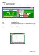
RS-232 PC Interface The Model 421509 Thermometer is supplied with a sophisticated Windows® software package on CDROM. A communications cable (meter to PC) is also supplied. The program allows the user to operate the meter remotely and view the readings from all three LCD fields on the PC monitor. The software also permits measurement data to be stored as text files on a PC. The data files can then be exported to spreadsheet or other programs for further manipulation (graphing, sorting, filing, etc.).
Operation 1. Select the correct COM port 2. Press the “START” button 3. Press the T1 INPUT, T2 INPUT or T1-T2 button to open the control window Button MAX MIN AVG REL HI/LO TYPE GRAPH Description Activate Max/Min reading with time Activate Average reading measurement Activate Relative mode Activate Hi/Lo limit comparative mode. The limit will also be visible on the graphical display as red (HI) and blue (LO) horizontal lines.
Record Function (Data Acquisition) Button FILE NAME USER FILE INTV LIST CLR REC Description Select Default or User Name Acquisition Saved in .xls format Sample rate from 1 to 65535 Enter the number of the lines to 15000 Clears the screen Starts data acquisition/Press stop recording for Data from 50 OFF to Importing Data from the Meter 1. Click the READ DATA button 2. The window will open and the data stored in the meter’s memory will automatically download to the PC.
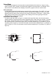
Battery Replacement Replace the battery when the low battery indication symbol appears on the upper left corner of the display. To replace the battery, remove the protective rubber holster to access the battery compartment. Remove the two screws that secure the rear battery compartment cover. Remove the old battery, install a new one, and replace cover. Warranty FLIR Systems, Inc.