USER GUIDE Coating Thickness Tester Model CG204
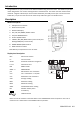
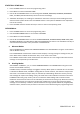
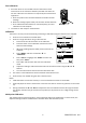
Introduction Congratulations on your purchase of the Extech CG204 Coating Thickness Tester. The CG204 is a portable meter designed for non‐invasive coating thickness measurements. The meter uses two measurement methods: magnetic induction (for ferrous metal substrates) and eddy current (for non‐ferrous metal substrates). Proper use and care of this meter will provide many years of reliable service. Description Meter Description 1. USB jack for PC interface 2. Measurement probe 3. Backlit LCD display 4.
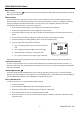
Quick Start Instructions Meter Power Press the power button to switch the meter ON. The display will switch ON. If the display does not switch ON, replace the batteries. Measurements Use the supplied film references and zero reference metal substrates to learn how the meter operates before moving to a professional application. The round metal substrate is the ferrous (magnetic) substrate and the rectangular shaped metal substrate is the non‐ferrous (non‐magnetic) substrate.
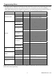
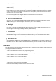
Programming Menu The meter can be configured and calibrated through simple button presses in the programming menu. Press the MENU button to access the menu and refer to the menu ‘tree’ below. The menu uses UP/DOWN, SELECT, BACK, & ESC presses for navigation and selection. In the table below the factory default settings are in bold with an asterisk. Each parameter is explained in detail in the subsequent sections.
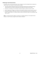
STATISTICAL VIEWS Menu 1. Press the MENU button to access the programming menu 2. Press SELECT to choose STATISTCAL VIEW 3. Use the UP and DOWN buttons to scroll through the AVERAGE, MINIMUM, MAXIMUM, NUMBER OF DATA, and SDEV (Standard Deviation) values for the stored readings. 4. ‘NO DATA’ will display if no readings are available for the meter to analyze. Stored readings will clear when the meter powers down unless the GROUP feature is used (refer to GROUP function explanation later in this section). 5.
c. Probe Used Select AUTO, Fe, or No Fe under PROBE USED in the OPTIONS Menu using the arrow buttons and the SELECT soft‐key. In the AUTO mode, the meter automatically activates the probe measurement method (ferrous or non‐ ferrous) based on the metal substrate that is being measured. When the probe is placed on a magnetic substrate it will work in the magnetic induction mode. If the probe is placed on a non‐ferrous metal it will work in the eddy current mode.
DELETE Menu The DELETE menus allows for deleting current data, all data, and group data. The following parameters are available in the DELETE Menu: Delete Current data: Deletes the current reading and updates the statistics (AVG, MIN, MAX, etc.) Delete All data: Delete all reading and statistical data. Delete Group data: This function duplicates the “Delete all data” function with additional, deletions of High alarm, Low alarm, and one‐ and two‐point calibrations. 1.
Calibration Calibration Types The meter is factory calibrated before shipment to the customer; however the customer should perform a zero calibration and a multi‐point calibration before any critical measurements are taken. The calibration options are listed below. Read the description for each and select the best match for a given application. 1. Zero Point Calibration: Perform before each measurement session. 2.
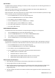
Zero calibration 1. Place the meter on an uncoated section of the material to be measured or on the reference substrate provided. Use either the Ferrous or Non‐Ferrous reference as required by the measurement application. a. Place the probe on the uncoated substrate and watch the LCD readings. b. When the readings appear stable, lift the meter off the substrate c. Press and Hold the Zero button for 2 seconds (beep). The Zero calibration is now complete. 2.
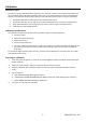
Calibrating for Shot‐blasted surfaces The physical nature of shot‐blasted surfaces results in higher than normal coating thickness readings. The mean thickness over the peaks can be determined as follows: 1. The meter should be calibrated according to the calibration instructions. Use a smooth calibration sample with the same curvature radius and the same substrate as the device to be tested. 2. Take approx. 10 readings on the uncoated, shot‐blasted sample to produce the mean value Xo. 3.
Statistical Analysis Considerations The meter calculates statistics from a maximum of 80 readings (For Group 1 through Group 4, a maximum of 400 readings can be stored). Note that readings cannot be stored when in DIRECT mode. However, statistics on these readings can still be calculated. When the meter is powered off or if the working mode is changed (in the programming menu), the DIRECT mode statistics will be lost. The following statistical values can be calculated: NO.
PC Interface This meter has the capability to connect to and communicate with a PC. To install and use the software, please refer to the instructions provided on the supplied CD‐ROM and/or the instructions provided in the HELP Utility within the software program. Check the software download page of the website www.extech.com for the latest version of the PC software and its operating system compatibility. Error Messages The following error messages will appear on the meter’s LCD if a problem arises.
Specifications Sensor probe Ferrous Non‐Ferrous Measurement principle Magnetic induction Eddy current principle Measuring range 0~1250μm 0~1250μm 0~49.21mils 0~49.21mils Accuracy 0~850μm: ±(3% + 1μm) 0~850μm: ±(3% + 1.5μm) (% of reading) 850μm ~1250μm: (±5%) 850μm ~1250μm: (±5%) 0~33.46mils: ±(3% + 0.039mils) 0~33.46mils: ±(3% + 0.059mils) 33.46mils ~49.21mils: (±5%) 33.46mils ~49.21mils: (±5%) 0~50μm: (0.1μm) 0~50μm: (0.1μm) 50μm ~850μm: (1μm) 50μm ~850μm: (1μm) 850μm ~1250μm: (0.