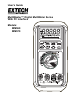
User’s Guide MultiMaster™ Digital MultiMeter Series With PC Interface Models: MM560 MM570
WARRANTY EXTECH INSTRUMENTS CORPORATION warrants this instrument to be free of defects in parts and workmanship for three years from date of shipment (a six month limited warranty applies on sensors and cables). If it should become necessary to return the instrument for service during or beyond the warranty period, contact the Customer Service Department at (781) 890-7440 ext. 210 for authorization. A Return Authorization (RA) number must be issued before any product is returned to Extech.
Introduction Congratulations on your purchase of Extech model MM560 or MM570 digital multimeter. Properly used, this meter will provide many years of reliable service. MultiMaster™ Meters provides high resolution, high accuracy, true rms measurements of AC Voltage and Current, DC Voltage and Current, AC+DC, Resistance, Frequency, Capacitance, Duty Cycle, dBm, Peak, %4-20, Diode, and Continuity. The MultiMaster™ also offers RS-232 PC Interface data acquisition capabilities as an option.
7. Use great care when making measurements if the voltages are greater than 25VAC rms or 35VDC. These voltages are considered a shock hazard. 8. Always discharge capacitors and remove power from the device under test before performing Capacitance, Diode, Resistance or Continuity tests. 9. Remove the battery from the meter if the meter is to be stored for long periods. 10. To avoid electric shock, do not measure AC current on any circuit whose voltage exceeds 1000V AC. 11.
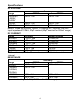
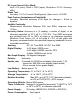
Specifications DC VOLTAGE Accuracy Range MM570 MM560 500.00 mV, 0.02% + 2d 0.03% + 2d 5.0000V, 50.000V 500.00V 0.04% + 2d 0.05% + 2d 1000.0V 0.05% + 2d 0.1% + 2d NMRR: >60dB @ 50/60Hz, CMRR: >120dB @ DC, 50/60Hz, Rs=1kΩ Input impedance: 10MΩ, 30pF nominal (80pF nominal for 500mV range) DC CURRENT Range Accuracy Burden Voltage 0.15% + 20d 500.00µA 0.15mV/µA 0.1% + 20d 5000.0µA 0.15mV/µA 50.000mA 0.15% + 10d 3.3mV/mA 500.00mA 0.1% + 20d 3.3mV/mA 5.0000A 0.5% + 10d 0.03V/A 10.000A* 0.5% + 20d 0.
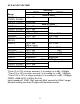
AC & AC+DC VOLTAGE Accuracy* MM570 Range 500.00mV, 1.5% + 40d 5.0000V, 50.000V 500.00V, 1000.0V unspecified MM560 20Hz to 45Hz unspecified 45Hz to 300Hz 0.8% + 60d 500.00mV 0.3% + 20d 5.0000V, 50.000V 0.8% + 20d 500.00V, 1000.0V 0.4% + 40d 300Hz to 5kHz 500.00mV 0.3% + 10d 5.0000V, 50.000V, 0.4% + 40d 500.00V 1000.0V 0.8% + 40d (300Hz-1kHz) 5kHz to 20kHz 500.00mV 0.5% + 20d 5.0000V, 50.000V 0.8% + 20d 500.00V 0.5% + 20d 1000.0V Unspecified 300Hz to 1kHz 0.8% + 40d 2.0% + 60d 1.
AC & AC+DC CURRENT Accuracy MM570 Range 500.00µA, 0.5% + 50d 5000.0µA 50.000mA, 500.00mA 5.0000A, 10.000A* 500.00µA, 0.7% + 50d 5000.0µA 50.000mA, 500.00mA 5.0000A, 10.000A* MM560 50Hz to 60Hz 1.0% + 40d Burden Voltage 0.15mV/µA 3.3mV/mA 0.03V/A 40Hz to 1kHz 1.0% + 40d 0.15mV/µA 3.3mV/mA 0.03V/A 1kHz to 10kHz Unspecified 500.00µA, 2.0% + 50d 0.15mV/µA 5000.0µA 50.000mA, 3.3mV/mA 500.00mA 5.0000A, Unspecified 0.03V/A 10.
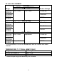
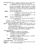
CAPACITANCE Range Accuracy* 50.00nF, 500.0nF 0.8% + 3d 1.0% + 3d 5.000µF 2.0% + 3d 50.00µF 3.5% + 5d 500.0µF 5.0% + 5d 9999µF *Accuracies with film capacitor or better FREQUENCY, AC LINE LEVEL Range 5.0000Hz to 200.000kHz Accuracy 0.002% + 4d Sensitivity 500mV range 5V range 50V range 500V range 1000V range 0.1V min 1V min 10V min 100V min 900V min FREQUENCY, LOGIC LEVEL Range 5.0000Hz to 2.00000MHz Accuracy 0.002% + 4d Sensitivity 2.5Vp square wave % DUTY CYCLE Range Accuracy Input Frequency 0.
DC Loop Current %4 to 20mA: 4mA = 0% (zero), 20mA = 100% (span), Resolution: 0.01%, Accuracy: ±25d Diode Test: Accuracy: 1%+1d, Current 0.8mA(typical), Open circuit: <3.5VDC Peak Capture (Instantaneous Peak Hold): Accuracy: Specified accuracy ±100 digits for changes > 0.8ms in duration Audible Continuity: Measurement threshold: Between 20Ω and 200Ω, response time: <100µs Accuracy Notes: Accuracy is ± (% reading + number of digits), or as otherwise specified, at 23°C ±5°C < 75% R.H.
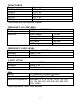
Auto Power Off: After 17 minutes of inactivity with no input signal. Power consumption during auto power off; 20µA Safety: The MultiMaster™ Series meters are intended for indoor use and are protected, against the users, by double insulation per EN61010-1 and IEC61010-1 2nd Edition (2001) to CAT III 1000V & CAT IV 600V. The meter (all versions) also meets UL3111-1(1994)* and CSA C22.2 No. 1010-1-92* to CAT III 1000V.
Meter Description (MM570 Shown) 1. Liquid Crystal display 2. Function push-keys 3. Rotary function switch 4. 10A/-T2 input jack 5. V/Hz/Ω/Cap/+T1 input jack 6. COM input jack/-T1 input 7. mA-uA current/+T2 input jack NOTE: RS-232 Optical interface is located on the top rear of the meter. Considerations & Features Average sensing RMS calibrated RMS (Root-Mean-Square) is the term used to describe the effective or equivalent DC value of an AC signal.
DC+AC True RMS DC+AC True RMS calculates both of the AC and DC components given by the expression when making measurement, and can responds accurately to the total effective RMS value regardless of the waveform.
Analog bar-graph The analog bar graph provides a visual indication of measurement like a traditional analog meter needle. It is excellent in detecting faulty contacts, identifying potentiometer clicks, and indicating signal spikes during adjustments. Default Functions The Multimaster™ will set the function last used as the default function. For example, if dBm is last used in the VAC position, the meter will display dBm the next time that function is selected.
Operation Measurement Considerations NOTICE: Read and understand all warning and caution statements listed in the safety section of this operation manual prior to using this meter. 1. Always move the rotary function switch to the OFF position when the meter is not in use. This meter has Auto Power OFF that automatically shuts the meter OFF if 17 minutes elapse without activity. 2. If "OL" appears on the display during a measurement, the measurement exceeds the range selected. Change to a higher range.
2. For current measurements up to 5000µA, set the function switch to the "µA" position and insert the red test lead into the mA-µA jack. 3. For current measurements up to 500mA, set the function switch to the "A/mA" position and insert the red test lead into the mA-µA jack. 4. For current measurements up to 10A, set the function switch to the "A/mA" position and insert the red test lead into the 10A jack. 5. Press the SELECT key momentarily to toggle between DC, AC and AC+DC 6.
6. For Continuity tests, if the resistance is less than the threshold (20Ω to 200Ω), an audible tone will sound.
Capacitance Measurements 1. Insert the black lead into the negative COM jack and the red test lead into the positive CAP jack. 2. Set the function switch to the " CAP" position. 3. Press the SELECT key momentarily to select Capacitance 4. Touch the test leads to the capacitor to be tested and read the measured value. Line Frequency Measurements 1. Connect and make a voltage or current measurement as described in the previous paragraphs. 2. Press the Hz key to select the Frequency (Hz) function. 3.
Diode Test 1. Insert the black lead into the negative COM jack and the red test lead into the positive CAP jack 2. Set the function switch to the " CAP" position. 3. Press the SELECT key momentarily to select the diode function 4. Touch the test probe tips to the diode or semiconductor junction you wish to test. Note the meter reading. 5. Reverse the test lead polarity by reversing the red and black leads. Note this reading. 6. The diode or junction can be evaluated as follows: a.
Relative mode Relative Zero allows the user to offset the meter by using the displayed value as the zero reference value. Practically all of the displayed readings can be set as the relative reference value including the MAX/MIN recording feature. Press the key momentarily to activate and to exit Relative Zero mode. Peak C capture mode Press PEAK key momentarily to activate the mode to capture voltage or current signal duration as short as 0.8ms.
RS-232 PC Interface This instrument is equipped with an optically isolated interface port (located on the rear of the meter). An optional WindowsTM software and interface package is available for data acquisition applications. This optional kit is required to connect the meter to a PC. The software provides digital, analog, and graphical data displays. Refer to the README file in the interface kit for further details.
Fuse Replacement 1. Remove the four screws from the case bottom and stand using a Philips head screwdriver. 2. Lift the end of the case bottom nearest the input jacks until it unsnaps from the case top 3. Replace the battery or blown fuse(s) 4. Replace the case bottom, and ensure that all the gaskets are properly seated and that the two snaps on the case top (near the display side) are engaged 5. Re-fasten the screws.