User's Guide Autoranging Multimeter Model MN47
Introduction Congratulations on your purchase of the MN47 MultiMeter. The MN47 offers AC/DC Voltage, AC/DC Current, Resistance, Diode, and Continuity and Temperature. Proper use and care of this meter will provide many years of reliable service. Safety This symbol adjacent to another symbol, terminal or operating device indicates that the operator must refer to an explanation in the Operating Instructions to avoid personal injury or damage to the meter.
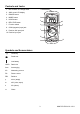
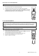
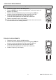
Controls and Jacks 1. Non-Contact AC voltage tester 1 2. 4000 count LCD display 3. RANGE button 4. MODE button 5. HOLD button 6. RELATIVE button 7. Function switch 2 3 5 4 6 8. COM (negative) input jack 9. Positive 10A input jack 7 10.
OPERATING INSTRUCTIONS WARNING: Risk of electrocution. High-voltage circuits, both AC and DC, are very dangerous and should be measured with great care. 1. ALWAYS turn the function switch to the OFF position when the meter is not in use. 2. If OL appears in the display, the value exceeds the range you have selected. Change to a higher range. NOTE: On some low AC and DC voltage ranges, with the test leads not connected to a device, the display may show a random, changing reading.
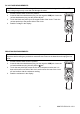
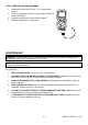
NON-CONTACT AC VOLTAGE DETECTOR WARNING: Always test the NCV function on a know live circuit before use 1. Turn the rotary switch to any measurement position 2. Hold the top of the meter very close to the voltage source as shown. 3. If voltage is present, the LED above the display will glowNOTE: The detector is designed with high sensitivity. Static electricity or other sources of energy may randomly trip the sensor. This is normal operation. AC VOLTAGE MEASUREMENTS WARNING: Risk of Electrocution.
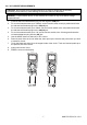
DC VOLTAGE MEASUREMENTS CAUTION: Do not measure DC voltages if a motor on the circuit is being switched ON or OFF. Large voltage surges may occur that can damage the meter. 1. 2. 3. 4. Set the function switch to the VDC position. Insert the black test lead banana plug into the negative COM jack. Insert the red test lead banana plug into the positive V jack. Touch the black test probe tip to the negative side of the circuit. Touch the red test probe tip to the positive side of the circuit.
AC / DC CURRENT MEASUREMENTS CAUTION: Do not make current measurements at 10 Amps for longer than 30 seconds. Exceeding 30 seconds may cause damage to the meter and/or the test leads. WARNING: To avoid electric shock, do not measure AC current on any circuit whose voltage exceeds 250VAC. 1. 2. 3. 4. 5. 6. 7. 8. 9. Insert the black test lead banana plug into the negative COM jack.
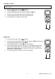
CONTINUITY CHECK WARNING: To avoid electric shock, never measure continuity on circuits or wires that have voltage on them. 1. 2. 3. 4. 5. 6. Set the function switch to the Ω position. Press the MODE button to select continuity •))). Insert the black lead banana plug into the negative COM jack. Insert the red test lead banana plug into the positive jack. Touch the test probe tips to the circuit or wire under test. If the resistance is < 30Ω, a tone will sound. DIODE TEST 1. 2.
CAPACITANCE MEASUREMENTS WARNING: To avoid electric shock, discharge the capacitor before measuring. 1. 2. Rotate the function switch to the CAP position. Press the MODE button to select capacitance (nF and a small value will appear in the display). 3. Insert the black test lead banana plug into the negative COM jack. Insert the red test lead banana plug into the positive CAP jack. 4. Touch the black test probe tip to one side of the device. Touch the red test probe tip to the other side of the device. 5.
TYPE K TEMPERATURE MEASUREMENT 1. 2. 3. 4. Rotate the function switch to the °F or °C temperature position. Insert the Temperature Probe into the negative COM jack and the TEMP jack. Place the temperature probe tip where needed. Read the temperature on the display. MAINTENANCE WARNING: To avoid electric shock, disconnect the test leads from any source of voltage before removing the back cover or the battery or fuse covers.
BATTERY INSTALLATION and LOW BATTERY INDICATION WARNING: To avoid electric shock, disconnect the test leads from any source of voltage before removing the battery cover. LOW BATTERY INDICATION + The icon will appear in the display when the battery voltage becomes low. Replace the batteries when this appears. BATTERY REPLACEMENT 1. Disconnect the test leads from the meter. 2. Remove the Phillips head screws (2) which secure the rear battery compartment cover. 3.
RANGE SPECIFICATIONS Function Range Resolution Accuracy DC Voltage 400mV 0.1mV ±(0.5% reading + 2 digits) (V DC) 4V 1mV 40V 10mV ±(1.2% reading + 2 digits) 400V 100mV 600V 1V ±(1.5% reading + 2 digits) AC Voltage 400mV 0.1mV ±(1.5% reading + 15 digits) (V AC) 4V 1mV ±(1.2% reading + 3 digits) (50/60Hz) 40V 10mV 400V 100mV ±(1.5% reading + 3 digits) 600V 1V ±(2.0% reading + 4 digits) DC Current 400μA 0.1μA ±(1.
Accuracy is stated at 65oF to 83oF (18oC to 28oC) and less than 70% RH. Function Range Resolution Accuracy Frequency 9.999Hz 0.001Hz 99.99Hz 0.01Hz 999.9Hz 0.1Hz 9.999kHz 1Hz 99.99kHz 10Hz ±(1.5% reading + 5 digits) ±(1.2% reading + 3 digits) 999.9kHz 100Hz 9.999MHz 1kHz ±(1.5% reading + 4 digits) Duty Cycle 0.1%-99.99% 0.1% ±(1.2% reading + 2 digits) Temperature -20ºC~+760ºC 1ºC ±(3.0% reading + 5ºC/9ºF) -4ºF~+1400ºF 1ºF Diode Test 0.
GENERAL SPECIFICATIONS Display 4000 count LCD with function indication Over-range indication “OL” is displayed Auto Power Off After 15 minutes (approximately) of inactivity Polarity Input Impedance ACV Bandwidth DCA voltage drop NCV voltage range Automatic (no indication for positive); Minus (-) sign for negative >1MΩ 45Hz to 450Hz 200mV 100VAC to 600VAC Audible continuity: Measurement Rate Audible threshold: less than 30Ω; Test current: <0.