User's Guide Autoranging Mini Multimeter Model MN16
Introduction Congratulations on your purchase of the Extech MN16 Autoranging Multimeter. This meter measures AC/DC Voltage, AC/DC Current, Resistance, Capacitance, Frequency, Diode Test, and Continuity plus Thermocouple Temperature. It features a rugged design for heavy duty use This meter is shipped fully tested and calibrated and, with proper use, will provide years of reliable service.
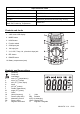
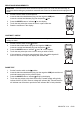
Input Protection Limits Function Maximum Input V DC or V AC 600VDC/AC mA AC/DC 400mA AC/DC A AC/DC 10A AC/DC (20A for 30 sec max every 15 min) Frequency, Resistance, Capacitance, Diode Test, Continuity, Temperature 250VDC/AC Controls and Jacks 1. 4,000 count LCD display 2. MODE button 3. HOLD button 4. Function switch 5. COM input jack 6. 10A input jack 7. V, Ω, CAP, Temp, Hz, μA and mA input jack 8. REL button 9. RANGE button 10.
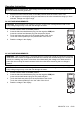
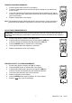
Operating Instructions WARNING: Risk of electrocution. High-voltage circuits, both AC and DC, are very dangerous and should be measured with great care. 1. ALWAYS turn the function switch to the OFF position when the meter is not in use. 2. If “OL” appears in the display during a measurement, the value exceeds the range you have selected. Change to a higher range. DC VOLTAGE MEASUREMENTS CAUTION: Do not measure DC voltages if a motor on the circuit is being switched ON or OFF.
DC CURRENT MEASUREMENTS CAUTION: Do not make 20A current measurements for longer than 30 seconds. Exceeding 30 seconds may cause damage to the meter and/or the test leads. 1. 2. 3. 4. 5. 6. 7. 8. 9. Insert the black test lead banana plug into the negative COM jack. For current measurements up to 4000µA DC; Set the function switch to the µA position and insert the red test lead banana plug into the µA jack.
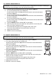
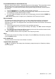
RESISTANCE MEASUREMENTS WARNING: To avoid electric shock, disconnect power to the unit under test and discharge all capacitors before taking any resistance measurements. Remove the batteries and unplug the line cords. 1. 2. 3. 4. 5. Set the function switch to the Ω position. Insert the black test lead banana plug into the negative COM jack. Insert the red test lead banana plug into the positive Ω jack. Press the MODE button to indicate “Ω" on the display.
TEMPERATURE MEASUREMENTS 1. 2. 3. 4. Set the function switch to the ºF or ºC position. Insert the Temperature Probe into the input jacks, making sure to observe the correct polarity. Touch the Temperature Probe head to the part whose temperature you wish to measure. Keep the probe touching the part under test until the reading stabilizes (about 30 seconds). Read the temperature in the display. Note: The temperature probe is fitted with a type K mini connector.
AUTORANGING/MANUAL RANGE SELECTION When the meter is first turned on, it automatically goes into Autoranging. This automatically selects the best range for the measurements being made and is generally the best mode for most measurements. For measurement situations requiring that a range be manually selected, perform the following: 1. 2. Press the RANGE button. The “Auto” display indicator will turn off. Press the RANGE key to step through the available ranges.
Maintenance WARNING: To avoid electric shock, disconnect the test leads from any source of voltage before removing the back cover or the battery or fuse covers. WARNING: To avoid electric shock, do not operate your meter until the battery and fuse covers are in place and fastened securely. This MultiMeter is designed to provide years of dependable service, if the following care instructions are performed: 1. KEEP THE METER DRY. If it gets wet, wipe it off. 2. USE AND STORE THE METER IN NORMAL TEMPERATURES.
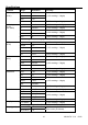
Specifications Function Range Resolution DC Voltage 4V 0.001V (V DC) 40V 0.01V 400V 0.1V AC Voltage (V AC) (50 / 60Hz) Accuracy ±(1.2% reading + 2 digits) 600V 1V ±(1.5% reading + 2 digits) 400mV* 0.1mV ±(1.5% reading + 15 digits) 4V 0.001mV ±(1.2% reading + 3 digits) 40V 0.01V 400V 0.1V 600V 1V ±(1.5% reading + 3 digits) ±(2.0% reading + 4 digits *400mV range is not autoranging DC Current (A DC) AC Current (A AC) Resistance Capacitance Duty Cycle 400μA ±(1.
Function Range Resolution Frequency 5.000Hz 50.00Hz 500.0Hz 5.000kHz 50.00kHz 500.0kHz 5.000MHz 0.001Hz 0.01Hz 0.1Hz 0.001kHz 0.01kHz 0.1kHz 0.001MHz Accuracy ±(1.5% reading + 5 digits) ±(1.2% reading + 3 digits) ±(1.5% reading + 4 digits) Sensitivity: >0.5V rms min. [ 1MHz; >3V rms > 1MHz NOTE: o o o o Accuracy is stated at 18 C to 28 C (65 F to 83 F) and less than 75% RH.
PER IEC1010 OVERVOLTAGE INSTALLATION CATEGORY OVERVOLTAGE CATEGORY I Equipment of OVERVOLTAGE CATEGORY I is equipment for connection to circuits in which measures are taken to limit the transient overvoltages to an appropriate low level. Note – Examples include protected electronic circuits. OVERVOLTAGE CATEGORY II Equipment of OVERVOLTAGE CATEGORY II is energy-consuming equipment to be supplied from the fixed installation. Note – Examples include household, office, and laboratory appliances.