USER MANUAL Insulation Tester + DMM Model MG320
Table of Contents 1. INTRODUCTION 3 2. SAFETY 3 3. METER DESCRIPTION 5 4. CONTROL BUTTONS 6 5. SYMBOLS AND ANNUNCIATORS 6 6. OPERATING INSTRUCTIONS 7 6.1 Display Backlight 6.2 Data Hold 6.3 Low Battery Indication 6.4 DC VOLTAGE MEASUREMENTS 6.5 AC VOLTAGE MEASUREMENTS 6.6 LOW RESISTANCE / CONTINUITY MEASUREMENTS 6.7 INSULATION RESISTANCE MEASUREMENTS 6.7.1 Disable Insulation Test Lock Mode 6.7.2 Insulation Resistance Test Time Setup 6.7.
1. Introduction Congratulations on your purchase of the MG320 True RMS Insulation Resistance CAT IV 600V DMM. The MG320 features a rugged design for heavy duty use. The MG320 measures Insulation Resistance, AC/DC Voltage, and Resistance. Insulation Resistance tests are automatic ranging with 5 test voltages from 50V to 1000V. The MG320 can store and recall up to 99 measurements.
PER IEC1010 OVERVOLTAGE INSTALLATION CATEGORY OVERVOLTAGE CATEGORY I Equipment of OVERVOLTAGE CATEGORY I is equipment for connection to circuits in which measures are taken to limit the transient over-voltages to an appropriate low level. Note – Examples include protected electronic circuits. OVERVOLTAGE CATEGORY II Equipment of OVERVOLTAGE CATEGORY II is energy-consuming equipment to be supplied from the fixed installation. Note – Examples include household, office, and laboratory appliances.
SAFETY STANDARDS This instrument is designed and produced strictly in accordance with the safety requirements for GB4793 electronic measuring instruments and IEC61010-1 safety standards. This instrument meets the double insulation over-voltage standard CAT IV 600V and pollution degree II. Failure to use the instrument as described in this user manual can weaken or negate the protections provided. Check the instrument, test leads, and test pen before use.
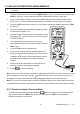
4. Control buttons 1. Data Hold on/off (short press) for AC/DC Voltage and Resistance modes only. Also for display Backlight on/off (long press) 2. Short press to Recall stored readings. Another short press to exit this mode. 3. Save reading (short press) and Clear all stored readings (long press) 4. Comparator (short press) and Zero (long press) 5. PI and DAR test mode selection (short 4 presses) 6.
6. Operating Instructions WARNING: Risk of electrocution. High-voltage circuits, both AC and DC, are very dangerous and should be measured with great care. 1. ALWAYS turn the function switch to the OFF position when the meter is not in use. 2. If “>” appears in the display during a measurement, the value exceeds the maximum range of the meter. 6.1 Display Backlight Press and hold the button to switch the backlight on or off. Excessive use of the backlight will cause the batteries to drain quicker. 6.
6.5 AC VOLTAGE MEASUREMENTS WARNING: Risk of Electrocution. The probe tips may not be long enough to contact the live parts inside some 240V outlets for appliances because the contacts are recessed deep in the outlets. As a result, the reading may show 0 volts when the outlet actually has voltage on it. Make sure the probe tips are touching the metal contacts inside the outlet before assuming that no voltage is present.
6.6 LOW RESISTANCE/CONTINUITY MEASUREMENTS WARNING: To avoid electric shock, disconnect power to the unit under test and discharge all capacitors before taking any resistance measurements. Remove the batteries and unplug the line cords. WARNING: To avoid electric shock, never measure resistance on circuits or wires that have a voltage. 1. 2. Set the function switch to the Ω position. Insert the black test lead banana plug into the negative COM jack (5).
6.7 INSULATION RESISTANCE MEASUREMENTS Note: Disconnect the unit under test from all power sources and isolate it from any stray resistance. 1. Connect the red test lead to the meter’s INSULATION (+) jack (7) and the black test lead to the EARTH (-) jack (6). Connect the probe end of the test leads to the circuit under test. 2.
6.7.2 Insulation Resistance Test Time Setup 1. Press the button to select the desired test time. Select from 15s, 30s, 1m, 15s/1m, 1m/30s, 10m, 15s/10m, and 30s/10m. Connect the meter to the device under test as shown in the Insulation Resistance test section above. 2. Press TEST to start the test. The test will end automatically after the time period has elapsed.
6.7.5 Comparator Utility Read and understand all operations and safety information contained in the Insulation Resistance and Continuity measurement sections and the Safety section before continuing. In Comparator mode the meter compares measurement to a preset reference values and displays PASS (measured value greater than reference value) or NG (measured value lower than reference value). 1. Connect the meter to the device under test as shown in the test section above. 2.
8. Maintenance WARNING: To avoid electric shock, disconnect the test leads from any source of voltage before removing the back cover, the battery, or fuse covers. WARNING: To avoid electric shock, do not operate your meter until the battery and fuse covers are in place and fastened securely. This Instrument is designed to provide years of dependable service, if the following care instructions are performed: 1. KEEP THE METER DRY. If it gets wet, wipe it off. 2.
9. Specifications Function Range Resolution Accuracy DC Voltage 600V 0.1V (2.0% reading + 3 digits) AC Voltage 600V 0.1V (2.0% reading + 3 digits) Specified from 5% of range to 100% of range Input impedance: 10M Min. Measured Voltage: 0.1V Frequency 50~400Hz Input protection: 600V DC and AC rms Low Resistance 20.00k & Continuity (1.5% reading + 3 digits) 0.01 Open-circuit voltage is 5.0V approx.
Insulation Resistance Test Voltage Outputs Test Short-circuit current current 250VAC/DC 1mA ≤2mA 100kΩ 250VAC/DC 1mA ≤2mA 10% steps (125~300V) 250kΩ 250VAC/DC 1mA ≤2mA 500V (0%~+10%) 10% steps (250~600V) 500kΩ 250VAC/DC 1mA ≤2mA 1000V (0%~+10%) 10% steps (500~1200V) 1MΩ 250VAC/DC 1mA ≤2mA Output Voltage Test Steps (50~120%) Load Overload 50V (0%~+10%) 10% steps (25~60V) 50kΩ 100V (0%~+10%) 10% steps (50~120V) 250V (0%~+10%) Note: Accuracy is stated at 23oC (75oF) and 45