User's Guide Wireless TRMS Multimeter and Insulation Tester Model MG300
Introduction Congratulations on your purchase of the MG300 True RMS MultiMeter Insulation Resistance Tester. This meter measures AC/DC Voltage, AC/DC Current, Resistance, Capacitance, Frequency (electrical & electronic), Duty Cycle, Diode Test, Insulation Resistance, and Continuity plus Thermocouple Temperature. The MG300 can store and recall measurement data and features a waterproof, rugged design for heavy duty use. This meter can transmit data wirelessly when linked to a PC.
SAFETY INSTRUCTIONS This meter has been designed for safe use, but must be operated with caution. The rules listed below must be carefully followed for safe operation. 1.
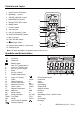
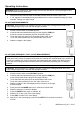
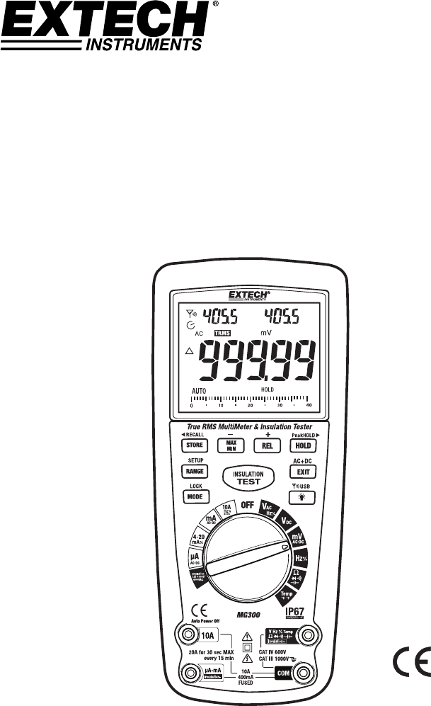
Controls and Jacks 1. 40,000 count LCD display 2. MAX/MIN ( - ) button 3. STORE () button 11 10 12 13 7 11. REL (+) button 12. EXIT (AC+DC) button 13. Backlight button 14. Positive and Insulation (+) input jack 8 14 9 15 15. COM input jack Note: Tilt stand and battery compartment are on rear of unit.
Operating Instructions WARNING: Risk of electrocution. High-voltage circuits, both AC and DC, are very dangerous and should be measured with great care. 1. ALWAYS turn the function switch to the OFF position when the meter is not in use. 2. If “OL” appears in the display during a measurement, the value exceeds the range you have selected. Change to a higher range. DC VOLTAGE MEASUREMENTS CAUTION: Do not measure DC voltages if a motor on the circuit is being switched ON or OFF.
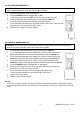
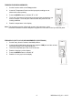
mV VOLTAGE MEASUREMENTS CAUTION: Do not measure mV voltages if a motor on the circuit is being switched ON or OFF. Large voltage surges may occur that can damage the meter. 1. 2. 3. 4. 5. 6. Set the function switch to the mV position. Press the MODE button to indicate “DC” or “AC” In AC mode, press and hold EXIT for two seconds to select ”AC+DC” Insert the black test lead banana plug into the negative COM jack. Insert the red test lead banana plug into the positive V jack.
AC CURRENT (FREQUENCY, DUTY CYCLE) MEASUREMENTS CAUTION: Do not make 20A current measurements for longer than 30 seconds. Exceeding 30 seconds may cause damage to the meter and/or the test leads. 1. 2. Insert the black test lead banana plug into the negative COM jack. For current measurements up to 4000µA AC, set the function switch to the µA position and insert the red test lead banana plug into the µA/mA jack. 3.
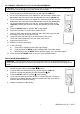
CONTINUITY CHECK WARNING: To avoid electric shock, never measure continuity on circuits or wires that have voltage on them. 1. 2. 3. 4. 5. Set the function switch to the Ω CAP position. Insert the black lead banana plug into the negative COM jack. Insert the red test lead banana plug into the positive jack. Press the MODE button to indicate“ ” and “Ω” on the display Touch the test probe tips to the circuit or wire you wish to check.
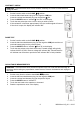
TEMPERATURE MEASUREMENTS 1. Set the function switch to the Temp position. 2. Insert the Temperature Probe into the input jacks, making sure to observe the correct polarity. 3. Press the MODE button to indicate “ºF” or “ºC” 4. Touch the Temperature Probe head to the part whose temperature you wish to measure. Touch the part under test with the probe until the reading stabilizes. 5. Read the temperature in the display. Note: The temperature probe is fitted with a type K mini connector.
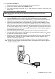
% 4 – 20mA MEASUREMENTS 1. Set up and connect the meter as described for DC mA measurements. 2. Set the rotary function switch to the 4-20mA% position. 3. The meter will display loop current as a % with 0mA=-25%, 4mA=0%, 20mA=100%, and 24mA=125%. INSULATION RESISTANCE MEASUREMENTS Note: Disconnect the unit under test from all power sources and isolate it from any stray resistance. 1. 2. 3. 4. 5.
AUTORANGING/MANUAL RANGE SELECTION When the meter is first turned on, it automatically enters the AUTO RANGE mode. This automatically selects the best range for the measurements being made and is generally the best mode for most measurements. For measurement situations requiring that a range be manually selected, perform the following: 1. 2. 3. Press the RANGE key. The “AUTO” display indicator will turn off. Press the RANGE key to step through the available ranges.
DISPLAY BACKLIGHT Press the key to switch the backlight on. The backlight will automatically switch off after the SET time has expired. Press the EXIT button to exit the backlight on mode. HOLD The hold function freezes the reading in the display. Press the HOLD key momentarily to activate or to exit the HOLD function. PEAK HOLD The Peak Hold function captures the peak AC or DC voltage or current. The meter can capture negative or positive readings as fast as 1 millisecond in duration.
PC WIRELESS COMMUNICATION 1. Install and launch the PC software (refer to the HELP utility contained in the software for more details) 2. Press and Hold the backlight/USB button for two seconds to enter RF wireless transmit mode 3. 4. 5. 6.
Maintenance WARNING: To avoid electric shock, disconnect the test leads from any source of voltage before removing the back cover or the battery or fuse covers. WARNING: To avoid electric shock, do not operate your meter until the battery and fuse covers are in place and fastened securely. This MultiMeter is designed to provide years of dependable service, if the following care instructions are performed: 1. KEEP THE METER DRY. If it gets wet, wipe it off. 2. USE AND STORE THE METER IN NORMAL TEMPERATURES.
REPLACING THE FUSES WARNING: To avoid electric shock, disconnect the test leads from any source of voltage before removing the meter cover. 1. Disconnect the test leads from the meter. 2. To replace the 500mA fuse only, remove the battery cover (four screws); the 500mA fuse will be visible and accessible. 3. To replace the 10A fuse, remove the six screws securing the rear cover and remove the rear cover. 4. Gently remove the old fuses and install the new fuses into the holders. 5.
Specifications Function DC Voltage AC Voltage (AC+DC) 50 to 1000Hz DC Current Range 400mV 4V 40V 400V 1000V Resolution 0.01mV 0.0001V 0.001V 0.01V 0.1V 400A 0.01A Accuracy (0.06% reading + 4 digits) (0.1% reading + 5 digits) 400mV 0.1mV (1.0% reading + 7 digits) 4V 0.001V 40V 0.01V 400V 0.1V (1.0% reading +5 digits) 1000V 1V All AC voltage ranges are specified from 5% of range to 100% of range 4000A 0.1A 40mA 0.001mA 400mA 0.01mA 10A 0.
Function Resistance Capacitance Frequency (electronic) Frequency (electrical) Duty Cycle Range Resolution 400 0.01 4k 0.0001k 40k 0.001k 400k 0.01k 4M 0.0001M 40M 40nF 400nF 0.001M 0.001nF 0.01nF 4F 0.0001F 40F 0.001F Accuracy (0.3% reading + 9 digits) (0.3% reading + 4 digits) (2.0% reading + 10 digits) (3.5% reading + 40 digits) (3.5% reading + 10 digits) 400F 0.01F 4mF 0.0001mF (5% reading + 10 digits) 40mF 0.001mF 40Hz 0.001Hz 400Hz 0.01Hz 4kHz 0.
Meg OHMS Terminal Voltage Range Resolution Accuracy Test current Short circuit current 125V (0%~+10%) 0.125~4.000 MΩ 0.001MΩ 4.001~40.00 MΩ 0.01MΩ +(2%+10) 40.01~400.0 MΩ 0.1MΩ +(4%+5) 400.1~4000 MΩ +(5%+5) 1MΩ 250V (0%~+10%) 0.250~4.000 MΩ 0.001MΩ (0%~+10%) +(2%+10) 4.001~40.00 MΩ 0.01MΩ +(2%+10) 40.01~400.0 MΩ 0.1MΩ +(3%+5) 400.1~4000 MΩ +(4%+5) 1MΩ 500V (0%~+10%) 0.500~4.000 MΩ 0.001MΩ 1000V +(2%+10) +(2%+10) 4.001~40.00 MΩ 0.01MΩ +(2%+10) 40.01~400.0 MΩ 0.1MΩ +(2%+5) 400.
Enclosure Shock (Drop Test) Diode Test Storage capacity RF transmit distance Transmitter Frequency Continuity Check Peak Temperature Sensor Input Impedance AC Response ACV Bandwidth Crest Factor Display Overrange indication Auto Power Off Polarity Measurement Rate Double molded, waterproof (IP67) 6.5 feet (2 meters) Test current 0.9mA maximum, open circuit voltage 2.8V DC typical 8000 records 10 meters (approx) 915MHz Audible signal will sound if the resistance is less than 35 (approx.), test current <0.
Warranty FLIR Systems, Inc. warrants this Extech Instruments brand device to be free of defects in parts and workmanship for one year from date of shipment (a six month limited warranty applies to sensors and cables). If it should become necessary to return the instrument for service during or beyond the warranty period, contact the Customer Service Department for authorization. Visit the website www.extech.com for contact information.
Garantie FLIR Systems, Inc. garantit que cet appareil Extech Instruments est exempt de défauts matériaux et de fabrication pendant un an à partir de la date d’envoi (une garantie limitée de six mois s’applique aux capteurs et aux câbles). Si le renvoi de l’appareil pour réparation devient nécessaire durant ou après la période de garantie, contactez le service client pour autorisation. Pour obtenir les coordonnées, visitez le site Web suivant : www.extech.com.
Garantía FLIR Systems, Inc., garantiza este dispositivo marca Extech Instruments para estar libre de defectos en partes o mano de obra durante un año a partir de la fecha de embarque (se aplica una garantía limitada de seis meses para cables y sensores). Si fuera necesario regresar el instrumento para servicio durante o después del periodo de garantía, llame al Departamento de Servicio a Clientes para obtener autorización. Visite www.extech.com para Información de contacto.