USER GUIDE True RMS Mini Clamp Meters MA61 60A AC Clamp Meter MA63 60A AC/DC Clamp Meter
Introduction Thank you for selecting the Extech Instruments True RMS Mini Clamp Meter. The MA61 measures AC Current while the MA63 measures AC and DC Current. Both meters also measure AC/DC Voltage, Frequency, Resistance, Capacitance, Diode, and Continuity. The Mini Clamp Meters measure current in three AC ranges 600mA, 6000mA, and 60A. The MA63 only measures DC current in two ranges 6000mADC and 60ADC.
Safety The product design meets IEC/EN61010‐1 and EN61010‐2‐033. Please read the User Guide before use and comply with all safety instructions. This product conforms to UL Standards 61010‐1, 61010‐2‐030, 61010‐2‐032, 61010‐2‐033 and is Certified to CSA standards C22.2 no. 61010‐1, 61010‐2‐030 and IEC standards 61010‐2‐032 and 61010‐2‐033. Safety Notices 1. Please use the clamp meter according to this User Guide otherwise the built‐in protections may be compromised. 2.
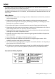
Meter Description 1. Clamp Jaws 2. Measured Conductor 3. NCV Non‐Contact Voltage Detector lamp 4. Function Select Switch 5. MODE Button 6. LCD Display 7. COM Input Test Lead Terminal 8. Positive Input Test Lead Terminal 9. REL (Relative) button on MA61; ZERO button on MA63 10. Display Hold / backlight button 11.
Function Switch Description MODEL MA61 1. NCV: Non‐Contact Voltage Detector 2. 60A AC Measurements 3. 600mA AC Measurements 4. 6000mA AC Measurements 5. Resistance, Diode, Continuity, and Capacitance Measurements 6. AC or DC Voltage and Frequency Measurement 7. POWER OFF selection 8. Function Selector Dial MODEL MA63 9. NCV: Non‐Contact Voltage Detector 10. 60A AC with Frequency or DC Measurements 11. 600mA AC with Frequency or DC Measurements 12.
Display Icon Descriptions Low Battery Trms True RMS measurement DC Direct current AC Alternating current AUTO ‐ ))) Automatic range Minus sign; negative reading Audible Continuity mode Diode test H Display hold Auto Power OFF (APO) icon (switches off when APO is disabled) ZERO/REL VFC EF Zero (MA63) and Relative (MA61) functions Variable Frequency Control (low pass filter) for AC Voltage/Current NCV (Non‐Contact Voltage) Detector (EF: Electromotive Force) mA, A Ampere: Unit of current mV, V
Operation Meter Power Caution: Do not use the meter with battery compartment open or unsecured. The clamp meter is powered by two (2) AAA batteries. The battery compartment is located on the back of the meter. The battery compartment is secured by one Phillips head screw. Refer to the Battery Replacement section later in this guide for more information. Automatic Power OFF (APO) The meter automatically switches off after 15 minutes of inactivity.
AC Current Measurements WARNING: To avoid electric shock, disconnect the test leads from the meter before making current measurements. CAUTION: Observe CAT II 600V, CAT III 300V with respect to Earth Ground for the Jaw. 1. Set the Function switch to the 600mA, 6000mA, or 60A range. 2. For the MA63, short press the MODE button to Select AC, Frequency (or DC) 3. Press the Trigger to open the clamp jaw. 4. Clamp onto a single conductor (fully enclosing it).
Frequency Measurements WARNING: To avoid electric shock, disconnect the test leads from the meter before making current measurements. CAUTION: Observe CAT II 600V, CAT III 300V with respect to Earth Ground for the Jaw. 1. Set the Function switch to the Hz position. 2. Press the Trigger to open the jaw and fully enclose one conductor. Refer to the Fig‐3 in the Current Clamp technique section above. 3. Read the Frequency measurement on the LCD in Hz.
DC Voltage Measurements 1. Insert the black test lead banana plug into the negative (COM) jack and the red test lead banana plug into the positive (V/Ω) jack. 2. Move the Function Switch to the V position. 3. Press the MODE button to select DC if necessary. 4. Touch the test probe tips to the circuit under test. Be sure to observe the correct polarity (red lead to positive, black lead to negative). 5. Read the voltage in the display. The display will indicate the proper decimal point and value.
Continuity Measurements 1. Insert the black test lead into the negative COM terminal and the red test lead into the positive terminal. 2. Set the function switch to the ))) position. 3. Use the MODE button to select the Continuity mode. Look for the Continiuty icon ))) on the display. 4. Touch the test probe tips across the circuit or component under test. Refer to Fig‐7 in the Resistance measurement section. 5. If the resistance is < 10 Ω, the beeper will sound.
Diode Test 1. Insert the black test lead banana plug into the negative COM jack and the red test lead banana plug into the positive jack. 2. Turn the function switch to position. Use the MODE button to select the diode function if necessary (the diode and voltage symbols will appear on the LCD when in Diode test mode). 3. Touch the test probe tips to the diode or semiconductor junction under test. Note the meter reading 4. Reverse the test lead polarity by reversing the red and black leads.
NCV Non‐Contact AC Voltage Detector CAUTION: Remove test leads from meter before attempting NCV tests. Always verify the NCV function on a known live circuit before performing tests. Do not use the NCV function if the display does not show EF when the function switch is turned to the NCV position. If the meter does not switch on when the NCV mode is initiated, please check the batteries.
Zero/Relative Measurements 1. Press ZERO (MA63) or REL (MA61) to enter the mode. The display will show the ZERO icon. 2. Now each time the ZERO/REL button is pressed the present measurement will zero and the beeper will sound. This mode is especially useful for DCA measurement zeroing. 3. In this mode, all subsequent measurements are displayed with respect to the reference measurement. For example, if a 20V reading is zeroed and a 30V reading is subsequently measured, the LCD will display 10V. 4.
Specifications General Specifications Display 6000 count LCD with multifunction indicators Full scale 6200 counts for Capacitance function Full scale 9999 counts for Frequency function LED lamp For Non‐Contact Voltage Detector Functions Current (ACA, DCA), Voltage (VAC, VDC), Resistance, Capacitance, Frequency, Non‐Contact Voltage detector, Continuity, and Diode test Polarity “‐“ indicates negative polarity (positive polarity assumed) Current sensor Hall effect Overload indication O.
Range Specifications Accuracy stated for ambient conditions 230C ±50C (73.40F ±90F) DC Current (MA63) Resolution Accuracy (of rdg + digits) Overload 6000mA 1mA ±(2.0% + 5d) 100A DC 60A 0.01A ±(2.0% + 3d) 100A DC AC Current Resolution 50/60Hz ≥100Hz ≤400Hz Overload 600.0mA 0.1mA ±(1.5% + 10d) ±(2.0% + 10d) 100A / 600VAC 6000mA 1mA ±(2.5% + 5d) ±(3.0% + 5d) 100A / 600VAC 60A 0.01A ±(2.0% + 5d) ±(2.5% + 5d) 100A / 600VAC VFC 600.0mA~60A 0.1mA~0.01A ±(4.
Accuracy stated for 5~100% of range; <20 digit residual reading for 600mA open circuit. AC Crest Factor may reach 3.0 at 4000 counts; for non‐sinusoidal waveforms the Crest Factor error increases per the following: Add 3% when the crest factor is 1~2; Add 5% when the crest factor is 2~2.5 Add 7% when the crest factor is 2.5~3 Frequency (Hz) Resolution Accuracy Overload Protect 10Hz to 60kHz 0.001~0.01kHz ±(0.