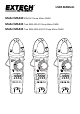
USER MANUAL Model MA440 400A AC Clamp Meter DMM Model MA443 True RMS 400 AC Clamp Meter DMM Model MA445 True RMS 400A AC/DC Clamp Meter DMM
Introduction Thank you for selecting the Extech EX44x Series 400A Clamp Meter. The MA440 is a 400A AC Clamp meter with a total of 9 functions. The MA443 is a 400A True RMS AC Clamp meter that offers 10 functions including TRMS AC measurements and Type K Thermocouple The MA445 is a 400A AC/DC True RMS Clamp meter with 11 functions including DC Current, TRMS AC measurements, and Type K Thermocouple. The MA44x series are hand‐held, 4000 count clamp meters.
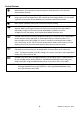
WARNINGS WARNINGS identify hazardous conditions and actions that could cause BODILY HARM or DEATH. 1. 2. 3. 4. 5. 6. 7. 8. 9. 10. 11. 12. 13. 14. 15. 16. 17. 18. 19. Before use, check the clamp meter and probe for damage or abnormal operation. Do not use the meter if probe insulation damage, meter display problems, abnormal meter functioning, etc. is observed. Never use the meter with the battery compartment open or with the meter housing disassembled in any way; otherwise a risk of shock will exist.
CAUTIONS CAUTIONS identify conditions and actions that could cause DAMAGE to the meter or equipment under test. Do not expose the meter to extremes in temperature or high humidity. Safety Symbols This symbol, adjacent to another symbol, indicates the user must refer to the manual for further information.
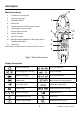
Description 11 Meter Description 1. Transformer current jaws 2. Jaw opening trigger 3. M (Mode) button 4. Backlit LCD 5. Control buttons (see descriptions below) 6. COM negative input terminal 7. Positive input terminal 8. Function selector 9. NCV alert symbol 10. Backlight button (MA440) or Work Light button (MA443 and MA445) 11. NCV sensor 1 2 10 9 8 3 4 Note: Battery compartment is located on back of meter 5 Fig.
Control Buttons Mode button: Short presses to step through the mode options for the selected measurement function HOLD and Backlight button (MA443/MA445): Short press to freeze/unfreeze reading. Long press to turn backlight ON or OFF.
Operation CAUTIONS Read and understand all of the Safety statements listed in the safety section of this manual prior to use. Powering the Meter 1. Move the function switch to any position to power the meter. Check the batteries if the unit fails to power ON. 2. Move the function switch to the OFF position to remove power to the meter. 3. The meter has an Auto Power OFF feature (APO) where the meter switches OFF after 30 minutes (MA440) or 15 minutes (MA443/MA445) of inactivity.
AC Current Measurements WARNING: Do not handle the meter above the finger/hand guard barrier. CAUTION: Observe CAT III 600V with respect to Earth Ground for the Jaw. 1. Rotate the function switch to the AC Current position ( for MA443 and MA445 or 4 /40 /400 for the MA440). For the MA440 start with the highest range setting (400A) and step down to lower ranges as needed, especially for signals that are of an unknown range. 2.
DC Current Measurements (MA445) WARNING: Do not handle the meter above the finger/hand guard barrier. CAUTION: Observe CAT III 600V with respect to Earth Ground for the Jaw. CAUTION: Measure in the temperature range of 0 ~ 40oC only. 1. Rotate the function switch to the DC Current position . 2. The A and the DC symbols will appear on the display indicating DC Amperes (Amps). The AUTO icon will also display indicating automatic ranging. 3.
AC and DC Voltage Measurements WARNING: Do not apply > 600VAC/DC between the meter terminals and ground. CAUTION: When connecting the test leads to the circuit or device under test, connect the black lead before the red lead; when removing the test leads, remove the red lead before the black lead. 1. Set the function select switch to the Voltage position . 2. Use the M (Mode) button to select AC or DC Voltage. 3.
Resistance Measurements WARNING: Please remove power to the circuit under test and discharge all capacitors before taking resistance or continuity measurements. The meter will display OL if the circuit under test is an open circuit of if the measurement exceeds the maximum range of the meter. Do not input a voltage >30V AC or DC. 1. 2. 3. Turn the function switch to the Resistance Ω position. Use the M (mode) button to select the ohm Ω display symbol.
Continuity Measurements WARNING: Please remove power to the circuit under test and discharge all capacitors before taking resistance or continuity measurements. The meter will display OL if the circuit under test is an open circuit of if the measurement exceeds the maximum range of the meter. Do not input a voltage >30V AC or DC. 1. Turn the function switch to the Continuity position. icon. 2. Use the M (mode) button to select the continuity display 3.
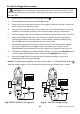
Capacitance Measurements WARNING: Please remove power to the circuit under test and discharge all capacitors before taking capacitance measurements. 1. 2. 3. 4. 5. 6. Turn the function switch to the position. Use the M (mode) button to select the capacitor display icon if necessary. Insert the black lead banana plug into the negative (COM) jack. Insert the red test lead banana plug into the positive jack. See Fig. 9. Touch the test probe tips across the circuit or component.
Diode Test WARNING: Please remove power to the circuit under test and discharge all capacitors before taking diode measurements. Do not input voltages > 30V DC or AC to the meter. 1. Turn the function switch to the position. 2. Use the M button to select the diode icon 3. Insert the black test lead banana plug into the negative (COM) jack and the red test lead banana plug into the positive (V) jack. See Fig. 10. 4.
Temperature Measurements (MA443 and MA445) WARNING: The supplied thermocouple is NOT rated for the entire specified temperature range of the meter. Please determine the range of temperature for the given application before attempting the use the supplied thermocouple. Obtain a different thermocouple if the range of the application exceeds the range of the supplied thermocouple. Do not measure temperature if the meter is in an environment outside the range of 18~28oC.
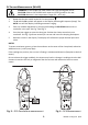
Non‐Contact Voltage‐Detector (EF/NCV) The area at the top of the clamp jaws is used for sensing AC voltage or an electromagnetic field. For the MA400, when the electrical field is > 100V and the distance is < 10mm, the beeper will sound and the red LED lamp will light. For the MA443 and MA445 when the electrical field is >100 V and the distance is < 10mm, the LCD will display dashes, the meter will beep, and the red LED lamp will light. The NCV lamp flashes at the same rate as the beeper.
Maintenance WARNING: To avoid electrical shock, disconnect the meter from any circuit and turn OFF the meter before opening the case. Do not operate with an open case. Cleaning and Storage Periodically wipe the case with a damp cloth and mild detergent; do not use abrasives or solvents. If the meter is not to be used for 60 days or more, remove the batteries and store them separately. Battery Replacement 1. Remove the Phillips head screw at the back (near center) of the meter. See accompanying diagram.
Specifications Electrical Specifications Accuracy is given as ± (% of reading + least significant digits) at 23C ±5C with relative humidity ≤ 75%. Accuracy is specified for a period of one year after calibration. 1. Temperature Coefficient is 0.1 x specified accuracy / C, < 18C (64.5F), > 28C (82.4F) 2. MA443/MA445 AC Functionality: ACV and ACA specifications are AC coupled, True RMS; For non‐ sinusoidal waveforms, additional accuracy Crest Factor (C.F.
Resistance 400.0 Ω 0.1 Ω ± (1.2% + 2 digits) 4.000k Ω 0.001k Ω 40.00k Ω 0.01k Ω 400.0k Ω 0.1k Ω 4.000M Ω 0.001M Ω ± (1.2% + 3 digits) 40.00M Ω 0.01M Ω ± (2.0% + 5 digits) ± (1.0% + 2 digits) 600V AC/DC Open Circuit Voltage: Approx. 1.5V (MA440) and 0.4V (MA443 and MA445) Continuity 400.0 Ω 0.1 Ω ± (1.2% + 2 digits) 600V AC/DC Continuity: Beeper ON < 30Ω. Beeper OFF >60Ω. Beeper unspecified >30Ω and <60Ω Diode 4.000V 0.001V Silicon PN junction 0.5 to 0.
‐40~40 oC 40~400 oC TEMPERATURE 1o C 400~1000 oC (TYPE K Thermocouple) ‐40~104 oF (MA443 and MA445) 104~752 oF ± (3.0% + 5 digits)* ± (1.0% + 3 digits)* 1o F 752~1832 oF 600V AC/DC ± (3.0% + 10 digits)* ± (1.0% + 6 digits)* *Does not include accuracy of the Type‐K temperature probe Non‐Contact Voltage Detector (NCV) ≥100Vrms; ≤10mm (0.4”) LED displays dashes, beeper sounds, and NCV lamp lights The tip of the meter offers optimum sensitivity 20 MA44x‐en‐GB_V1.
General Specifications Display Polarity Over‐range indication Conversion rate Clamp Sensor Type Test position error LCD 4000‐count multi‐function backlit LCD Automatic display of positive and negative polarity “OL” or “‐OL” is displayed 3 updates per second Coil induction (MA440); Hall Effect (MA443 and MA445) Additional error of ±1.