
Instruction manual


9 382860 Ver. 1.5 2/01
6. MEASUREMENT INSTRUCTIONS
6.1 Voltage AC/DC Measurements (True RMS for AC Voltage)
Attention: Never exceed the maximum input limits (1000VDC or 750 VAC
rms).Keep hands away from circuits where 25 VAC rms or 35 VDC exists.
To measure DC / AC voltage proceed as follows:
1. Set the rotary function switch to the desired position (mV or V)
2. Press the DC/AC key until the desired units are displayed (AC or DC).
3. Connect the test-lead tips to the object under test (load, circuit etc.)
4. Read the LCD
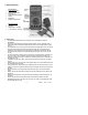
AC / DC Voltage Displays
During True RMS AC voltage measurements, the right-most sub-LCD display will
show the dB-value of the AC voltage, the middle sub-display shows the frequency
and the main display the ACV measurement. During DC voltage measurements,
the left sub-display updates the measurement 1 second later than the Main LCD,
the middle sub-display 2 seconds later, and the right sub-display 3 seconds later.
6.2 AC / DC Current Measurements (True RMS AC Current)
1. Select the desired Current range via the rotary switch (4 mA / 400 mA / 20 A).
2. Press the DC/AC button to select AC or DC Current units
3. “Break” the circuit to be measured and connect the test-leads in series with
circuit under test.
4. Power the device to be measured (circuit load etc.) and read the current on
the LCD. During AC current measurements, the middle sub-display will show
the frequency of the measurement and the main display indicates the current
measurement.
5. During DC current measurements, the left-most sub-display is updated one
second later than the main LCD. The middle sub-display two seconds later
and the right sub-LCD three seconds later.
Attention: Never measure current in circuits where over 250 VDC/VACrms may be
present. The meter fuses are designed for 250 V max. Measure circuits in which
15A fuse protection is provided only. Never measure circuits where Power
exceeds 4000 VA. Current measurements of 20A may only be taken for 30
seconds at 15 minute intervals (DO NOT exceed 20A).
6.3 Continuity Test
Continuity is a low resistance test permitting the testing of fuses, bulbs, test leads,
cable, circuits, etc. Set the rotary switch to the Ohm position and press the DC
Ohm/AC button until the music symbol displays. Connect the test-lead tips to the
device under test. If the resistance is < approx. 40ohms an audible tone sounds.
The left sub-LCD updates one second later than the main LCD, the middle sub-
display 2 seconds later, and the right-most sub-display 3 seconds later.
6.4 Resistance Measurements
Attention: Make sure all objects, circuits and
components under test are NOT powered!
1. Set the rotary switch to the Ohms position. Press the AC/DC key so that the
continuity musical symbol does NOT appear on the LCD.