
Instruction manual


6 382860 Ver. 1.5 2/01
5. BASIC METER OPERATION
5.1 Quick Start
• Connect the test leads to the meter
• Press the “ON/OFF” key to power the meter.
• Turn the rotary function switch to the desired measurement position. The
meter is now ready for “normal” measurement operation.
• To select an advanced function, press the FUNCTION key. The available
functions will appear on the top of the LCD display. Press FUNCTION again to
scroll through this function list. Press the SET/RESET key to select an
advanced function. These functions are explained in detail in Section 5.4
• To exit this menu, press the SET/RESET key twice (in some of the modes you
may have to press the FUNCTION key after the two SET/RESET key
presses).
5.2 Function Key Explanations
• ON/OFF Key: Press the “ON/OFF” key to toggle the meter ON and OFF
• FUNCTION Key: Press once to enter the advanced function menu. The
user can then select Data Hold DH, Range Hold RH, Auto Hold AH, Relative
REL, Memory MEM, Recall RCL, and Compare CMP functions. Each
function is explained in detail in Section 5.4.
• SET/RESET: Used for advanced features explained in Section 5.4.
• DC/AC Ohms/Continuity Key: Press this key to: Toggle between DC/AC
units and switch from resistance measurement to audible continuity check
modes
• UP/DOWN Keys: Used to:
1. Enter reference values in the REL or CMP modes
2. Address stored values in the MEM and RCL modes
3. Manually set the measurement range in the R-H function mode
4. Scroll through advanced Functions list (UP=forward,
DOWN=backward)
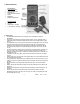
• BACKLIGHT ADJUST Key (circular, blue-colored button): Press this key
to deepen the LCD backlight effect. The backlight extinguishes after a 15-
second period of non-use to save battery life and illuminates again when a
keypress is sensed by the meter.
5.3 Input Terminal Designations
• Transistor Socket hFE (PNP NPN)
This terminal, located to the right of the Rotary Selector Switch, is where
transistor devices are inserted for testing. The eight pole transistor terminal is
lettered symmetrically with (E) Emitter, (B) Base, and (C) Collector. Insert the
transistor pins according to transistor type. Remember to remove any voltage
to components before measuring.
• Multi-Purpose Capacitor/Temperature Input Socket PLUS CMOS Signal
Output
This socket is located to the left of the Rotary Selector Switch. Discharged
capacitors and Type K temperature probes to be measured are inserted in
here. Observe correct polarity. The CMOS output signals are also available
here (see Section 8).
• 20A Input Terminal
For DC/AC current measurements to 20A max, insert the Red test-lead to this
input socket.
Attention: During current measurements the rotary switch must not be set to
voltage positions.