
Instruction manual

12 382860 Ver. 1.5 2/01
4. Now connect the other end of the black test-lead to the “ground” point of the
digital circuit and the red test-probe to the supply voltage point (V+ or Vcc)
5. When all leads are connected, press the SET/RESET key to save the “High”
Reference Level.
6. With the black test-lead-at ground, move the red test-probe from the supply
voltage to the desired test points. The multimeter will immediately display one
of the three modes. HIGH MODE: If the level exceeds 70% of the stored
supply voltage “Hi” is displayed. LOW MODE: If the level falls below 30% of
the stored supply voltage, “Lo” is displayed. PASS MODE: If the level is
between the reference values (31% and 69% of the supply voltage), “----“ is
displayed.
7. POWER MEASUREMENTS
For the measurement of power, the Power Adaptor (included) is required. This adaptor
consists of a three-prong plug and three-prong socket on one end (for connection
to loads under test) and a multi-plug on the other end (for insertion into meter's
input terminals).
7.1 Test Procedure
1. The Power Adaptor must be connected to the meter before Power
measurements can be made. Once connected, set the Rotary Switch to the
Power position.
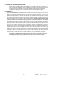
2. Connect the multi-plug side of the adaptor to the meter's input terminals. The
multi-plug is labeled with '20A' on the left, 'COM' in the middle, and 'V/ohms'
on the right. Always connect the correct contacts for all plug connections. The
labeling on the Power Adaptor matches the meter's labeled input terminals for
convenience.
3. Connect the appliance/load under test (not powered) to the socket of the
Power Adaptor.
4. Power the load under test by inserting the three-prong plug into a 117VAC
outlet. Readings can now be observed on the LCDS.
5. The maximum AC current that the meter can accept is 16A for short periods of
time (30 seconds or less). Never exceed this limit. 12A can be safely
monitored continuously.
WARNING: If the connection between adpator and meter is incorrect, severe meter
damage will result. In addition, a risk of electric shock exists. Finally, DO NOT select
any other range other than POWER while the adaptor is connected to the meter.
Serious meter damage and injury can occur.
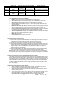
7.2 Three Modes of Power Measurement Displays
There are three modes of Power Measurement Displays. These modes have
different Main LCD and Sub-LCD displays related to power. Mode 0 is the initial
mode that the meter will be in when the POWER position is selected with the
Rotary Switch. A zero will display to the upper left of the left-most sub-LCD
indicating Mode 0. Use the UP and DOWN arrow keys to scroll through modes 0
through 2. The digit to the upper left of the left-most sub-LCD indicates the present
mode. Refer to the Table below for an overview of the display modes for the Main
LCD and the three Sub-LCDs. Then refer to the explanations below for
accumulated watts, cost, etc.