
User`s guide

MA220-en-EU_V1.9 8/14
4
Operation
Notice: Read and understand all WARNING and CAUTION statements listed in the safety section
of this operation manual prior to using this meter. Set the function select switch to the OFF position
when the meter is not in use.
DC/AC Current Measurements
Warning: Disconnect the test leads from the meter before making current
clamp measurements.
1. Set the Function switch to the 400ADC, 40ADC, 400AAC or 40AAC
range. If the range of the measured is not known, select the higher range
first then move to the lower range if necessary.
2. For DC current measurement, press the ZERO key to null the meter
display.
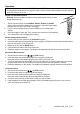
3. Press the trigger to open jaw. Fully enclose one conductor to be measured.
4. The clamp meter LCD will display the reading.
DC/AC Voltage Measurements
1. Set the rotary function switch to the Volts/Hz/% position.
2. Insert the black test lead banana plug into the negative (COM) jack and the red test lead banana
plug into the positive (V/Temp) jack
3. Select AC or DC with the MODE button
4. Connect the test leads to the circuit under test
5. Read the voltage on the display. The display will indicate the proper decimal point and value.
Resistance Measurements
1. Set the function switch to the
•))) CAP position.
2. Insert the black test lead banana plug into the negative (COM) jack
Insert the red test lead banana plug into the positive (V Temp jack.
3. Touch the test probe tips across the circuit or part under test. It is best to disconnect one side of
the part under test so the rest of the circuit will not interfere with the resistance reading.
4. Read the resistance on the display. The display will indicate the proper decimal point and value.
Continuity Check
1. Set the function switch to the
•))) CAP position.
2. Push the mode button to indicate •))) on the display.
3. Insert the black lead banana plug into the negative (COM) jack
Insert the red test lead banana plug into the positive (V) jack.
4. Touch the test probe tips to the circuit or wire you wish to check.
5. If the resistance is less than approximately 150, the audible signal will sound. If the circuit is
open, the display will indicate “OL.”.