User Manual High Definition VideoScope Model HDV600 Additional User Manual Translations available at www.extech.
Introduction Congratulations on your purchase of this Extech HDV600 series Video Borescope. This instrument is designed for use as a remote inspection device. It can be used to peer into tight spots, record and playback real-time video and images. Typical applications include HVAC inspection, automotive inspection, cable routing, and automotive/boat/aircraft inspection. The monitor is designed with dual left or right handed controls for maximum flexibility and is available with a full line of accessories.
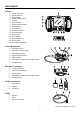
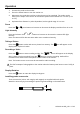
Description Monitor 1. 2. 3. 4. 5. 6. 7. 8. 9. 10. 11. 12. 13. 14. 15. 16. Probe connector Camera button Video button Rotate image button Display Zoom buttons Light intensity buttons Power Button Scroll buttons Selection buttons USB connector Microphone SD card slot Video output jack Reset button AC adaptor connector Articulating Probe 1. Articulation knob 2. Articulation tension knob 3. Articulating camera 4. Light intensity buttons 5. Power button 6. AC Adaptor and extension cable sockets 7.
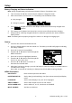
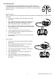
Setup Battery Charging and Status Indication: Note: A fully charged battery will allow approximately 5 hours of continuous use. 1. Turn the meter off and then connect the AC adaptor to charge the meter. 2. After several hours, turn the meter on. The battery icon will indicate either: A: Fully charged B: Charge in progress 3. If the battery is charged, remove the AC adaptor and observe that the fully charged 4 bar icon appears. 4.
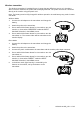
Operation 1. Connect the probe to the monitor. 2. Press the Power button to turn the monitor on. 3. Maneuvere the probe into position to view the area to be examined. The probe can be bent into the shape of the area to be examined. Optimum focus distance is 2 to 6cm (0.79 to 2.3”) 4. Optimum focus distance is probe dependent, but the typical range is 2 to 6cm Zoom Press the or zoom buttons to increase or decrease the display resolution from 1X to 2X.
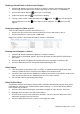
Articulating probe The articulating probe, with adjustable tip angle, is used for improved viewing angles and optimum inspection when the probe is inserted into the inspection location. The articulating probe is available in a direct (wired) or wireless version. Wireless version Note: The battery must be fully charged for wireless operation. A weak battery may result in meter shut down. 1. Connect the AC adaptor to the transmitter and charge the battery. 2.
Wireless transmitter The wireless transmitter is intended for use in areas that are difficult to access or in situations when is hard to maneuver the probe with the display attached. The probe can also be connected directly to the monitor using the patch cord. Note: The battery must be fully charged for wireless operation. A weak battery may result in meter shut down. Wireless Mode 1. Connect the AC adaptor to the transmitter and charge the battery. 2. Attach the probe to the transmitter. 3.
Viewing a Stored Photo or Video in the Display 1. Press the ▲ button to access the pictures or videos in memory. Each button press will step through the files with the file number appearing on the screen (i.e. IMG00005) 2. Pictures will appear with the 3. Videos will appear with the 4. To play a video, select a video file and press the during playback. Press the appear. photo icon on the display. film icon on the display. button. The play icon will appear button again to pause playback.
Reset button If the monitor becomes unresponsive due to an EMI field or other magnetic event, use a paper clip or other pointed object to press the RESET button located on the bottom panel Rear stand The rear stand can be set to three positions. Lower (stored), middle position for bench viewing and upper position for hanging. FCC Information This device complies with part 15 of the FCC rules. Operation is subject to the following two conditions: 1. This device may not cause harmful interference 2.
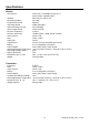
Specifications Monitor 14.5cm (5.7”) Viewable 13.5cm (5.3”) Active matrix, 640x480 pixels Interface Mini USB 1.1 and AV out Recording medium SD Card Compression format MPGE4 Still image format JPEG (640x480) Video Recording Format AVI (640x480) Video output Format NTSC and PAL Receiver Frequency 2.4GHz Receiver Sensitivity -87dBm (SNR = 42dB, Fmod = 15kHz) Video System NTSC / PAL Data Video / Audio Audio type Stereo Tripod mount On rear, Accepts standard tripod screw Battery 3.
Camera Imaging Sensor Video Format Brightness Control Lamp Type Interface Ingress protection Operating Temperature CMOS NTSC Manual LED Composite Video IP67 -20°C to 70°C (-4°F to 158°F) Probes and Cameras Articulation Accessories Part Number HDV-TX1 HDV-WTX1 HDV-TX2 HDV-WTX2 HDV-4CAM-1FM HDV-5CAM-1FM HDV-5CAM-3F HDV-5CAM-3FM HDV-5CAM-10F HDV-5CAM-1RM HDV-5CAM-3R HDV-5CAM-3RM HDV-25CAM-10G HDV-25CAM-30G 240°±20° manual tip articulation Mirror, magnet and anti-snag Ball (excluding 25mm diameter cables) D