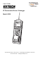
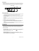
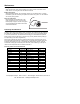
User's Guide IR Thermometer Printer / Datalogger Model 42580 Datalogging/ Printing IR The #5: 01:16-03 76.6°F 02: ---.-°F 03: ---.-°F 05-16-03 42580 rmometer LOGGING 11:19:59 11:20:00 Test Equipment Depot - 800.517.8431 - 99 Washington Street Melrose, MA 02176 FAX 781.665.0780 - TestEquipmentDepot.
Introduction Congratulations on your purchase of the Extech 42580 IR Thermometer PrinterDatalogger. This device measures temperature using a non-contact IR sensor. The Datalogger feature stores up to 100 readings in each set (4 sets total) for a total of 400 readings. The Printer provides a hard copy of individual readings or entire data sets. PC software permits downloading of data for further analysis. Careful use of this meter will provide years of reliable service.
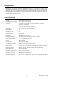
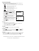
Meter Description 1. Laser pointer beam 2. Non-contact temperature sensor 3. LCD Display 4. Push-button keypad 5. Printer paper and paper compartment 6. RS-232c TTL output jack 7. AC Adapter jack 8. Battery compartment (rear) Safety • Use caution when the laser pointer beam is on • Do not point the beam toward anyone's eye or allow the beam to strike the eye from a reflective surface • Do not use the laser near explosive gases or in other potentially explosive areas 42580 Version 2.
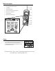
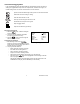
Operation Setup The Setup Screen provides access to the LCD Contrast, Printer Contrast, Emissivity setting, Temperature Units and setting of the date and time. 1. Press the button to access the setup screen. 2. Press the 3. The programmable parameters are as follows: 4. or key to move the 1 cursor to the desired position. • LCD Cont: Adjust the LCD contrast (0-5) using the numeric keypad. • Prn Cont: Adjust the print contrast (0-9) using the numeric keypad. • Emi.
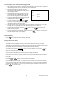
Field of View The meter’s field of view is 8:1, meaning that if the meter is 8 inches from the target, the diameter of the object under test must be at least 1 inch. Other distances are shown below in the field of view diagram. Refer to the chart printed on the meter for more information. Diameter of Spot 0.5” 4” 2” 1” Laser Beam 0.63” 4” Sensor Beam 8” 16” 32” Distance to Object Measurement Notes 1.
Manual Data Storage Mode The Model 42580 can store 99 readings in each of 4 sets numbered #1 through #4. The function of the buttons in the Manual Datalogging mode are: Opens the manual data storage mode, Opens a set and clears the data. Selects the set # for recording or viewing. Prints the stored records in a set. Scroll up or down through the records in a set. Stores the temperature reading. 1 to Z Alpha-numeric label entry (9 buttons). 1. Press the button to enter the manual data storage mode.
Automatic Datalogging Mode In the Auto Datalogging mode the Model 42580 can automatically measure and store 99 readings at a programmed sample rate. Four separate sets, numbered 5 through 8, can hold 99 readings each. The function of the buttons in the LOG mode are: Opens the automatic data storage mode, opens a set and clears the data Selects the set # for recording or viewing. Prints the stored records in a set. Scroll up or down through the records in a set. Stores Start time, Stop time and Log rate.
Recording Data in the Automatic Datalogging Mode 1. After preparing a data set and configuring the datalogger, place the meter in position to take readings (tripod mount is provided on rear of instrument). 2. Recording will begin on the date and time programmed at the BEGIN and START lines in the ‘Configure Screen’. 3. The Datalogger will record everyday from the START time to the SUSPEND time. The last day is the date programmed in the END line. #5 01: o 79.2 F 02: o 79.3 F 4.
Maintenance Cleaning Wipe instrument with damp cloth as needed. Do not apply solvents or abrasives to the meter. Store in a cool dry place with the batteries removed. Battery Replacement When the batteries weaken, the LCD display will dim or go completely blank. To replace the batteries, open the rear battery compartment and insert four (4) new 1.5V ‘AA’ batteries with correct polarity position.
Software System Requirements • Hardware Requirements: 486 PC or better with COM 1 and COM 2 Serial ports • Operating System Compatibility: Windows TM 95/98/NT/2000/XP Hardware Connection The IR Thermometer connects to a PC with the supplied DB-9 to 3.5mm mini-plug (mono) interface cable. The DB-9 end connects to the PC serial com port. The mini-plug end connects to the IR Thermometer. Software Installation The instructions on how to install the optional software are printed on the Software CD label.
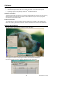
Software Operation When the program is started the meter and PC begin communicating. The main software screen appears. Buttons: Clear File Save Load File Print Set Selector Download Upload Entering Descriptions for Manual Recordings The 42580 has the capability of storing a 14 character label with each record to help in organizing the data collected. The label can be entered either before or after the readings are made.
Downloading Sets from the Meter Sets previously recorded by the IR Meter can be downloaded individually or as a group. With the meter connected to the PC and the software running To download an individual set: 1. 2. 3. On the toolbar Click on the set selector drop down screen Click on a set Click on the download button To download all sets simultaneously: 1. 2.
Save File The SAVE FILE icon is the second icon on the left (floppy disk symbol). Click on this icon to save recorded data as a text file. When clicked, the PC will prompt for a filename and location. Once saved, this file can be opened in other programs such as spreadsheets, word processors, and databases. Load File The OPEN FILE icon is located third from left. Double Click to open a file that has already been saved. Please note that in order to view, the file must be viewed in the same set location (i.