USER GUIDE Hot Wire CFM/CMM Thermo-Anemometer Model AN500 ft/min o F
Introduction Thank you for selecting the Extech Hot Wire CFM/CMM Thermo-Anemometer. This instrument measures air flow and temperature by placing the sensor into an airway such as a duct or a vent. The sensor is situated at the end of the telescoping wand for convenience. This device is shipped fully tested and calibrated and, with proper use, will provide years of reliable service. Please visit our website (www.extech.com) to check for the latest version of this User Guide.
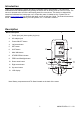
Push-button Description Power: Switches the meter ON and OFF C/F: Select the temperature units MAX/MIN: Press to Record and track the highest (MAX) and lowest (MIN) reading STORE: Store readings into memory RECALL: Display STORED readings UNIT: Air velocity units or airflow units of measure ZERO: Press to zero the display BACKLIGHT: Turn LCD backlight ON and OFF SET: Atmospheric compensation setting or airflow parameters setting 5 ◄►▲◄: Atmospheric compensation adjustment arrows
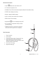
Operation Initialization and Zero The meter should always be zeroed at temperature before use using the ZERO button. Do not rely on the initial zero display. Notes: The meter does not display negative numbers. Open antenna to desired length. 1. Connect the sensor to the input jack on top of the meter and open antenna to desired length. 2. Switch the meter ON using the Power button. The meter will perform a self-test during which the display will show SELF CHECK. 3.
Auto Power OFF The meter is equipped with an Auto Power OFF (APO) feature. The meter will automatically switch OFF after 10 minutes of inactivity (no button pressed). Press and hold the POWER button for 1 second to disable the APO feature (the APO display icon will switch OFF). When the meter is powered ON for the next session, the Auto Power OFF feature will be engaged again. Change Units of Measure 1.
Zero Adjustment Press and hold the ZERO button for 1 second to zero the reading. Backlight Press the Zero/BL button at any time to turn on/off the backlight. Airflow Parameters Settings 1. While in airflow measurement mode press and hold SET for 1 second to enter next step. 2. Momentarily press the ►or ◄ button to choose circle or rectangle function. 3. Press SET to enter next step. 4. Press ▲ or ▼ to adjust R in circle mode or L and W in rectangle mode. Adjustment will be from 0.0-101.
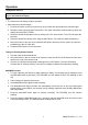
Battery Replacement When the displayed battery symbol appears empty or begins to blink, replace the batteries as soon as practical. If battery voltage is too low the meter will not switch ON. The battery compartment is located on the rear of the instrument (behind the tilt stand) secured by one Phillips head screw. 1. Open the rear battery compartment by first swiveling out the tilt stand. 2. Remove the Phillips head screw. 3. List the compartment cover to access the batteries. 4. Replace the six ‘AA’ 1.
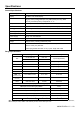
Specifications General Specifications Circuit configuration Custom one-chip LSI microprocessor circuit Display Dot Matrix LCD backlit display Measurements m/s (meters per second), km/h (kilometers per hour), ft/min (feet/per minute), knots (nautical miles per hour), MPH (miles per hour), CMM (m3/min), and CFM (ft3/min), Temperature: °C, °F Temperature sensor Two temperature sensors on glass pad Min/Max Recording Capture Maximum (MAX), Minimum (MIN), and Average (AVG) readings Datalogger 36 readin
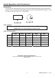
Useful Equations and Conversions Area equations The volume of air flowing through a duct or vent can be determined by taking the area of the duct in square units (i.e. square feet) and multiplying this value by the measured linear velocity (i.e., feet 2 3 per minute).