
Printer User Manual

Page 21
3.1.1 MSP SERIES - SERIAL COMMUNICATION PROTOCOL
Two communication protocols are supported by the MSP printer series - SERIAL BUSY
PROTOCOL and XON/XOFF PROTOCOL.
3.1.2 MSP SERIES - SERIAL BUSY PROTOCOL
In this mode, Pins 4 (RTS - From Host ) and 5 (CTS - From Printer) are used to control
data flow to and from the printer. This protocol is available for serial RS232C version
printers.
The <RTS> signal from the Host (pin #4) is used to enable the printer, the printer raises
<CTS> (pin #5) when it is ready to accept data.The printer lowers <CTS> line when
either the Print Buffer has less than 64 unused locations or when TEST OR FEED is
selected. The <RTS> signal is monitored during data transmission from the Printer to
Host. The printer transmits data to Host only if <RTS> is high.
3.1.3 MSP SERIES - XON/XOFF PROTOCOL
The Printer transmits XON when it is ready to accept data, and XOFF for conditions A
and B listed above. Under XON/XOFF protocol, the data flow out of the printer's Serial
Port is halted on receipt of XOFF from Host and resumed on receipt of XON.
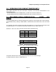
3.1.4 MSP SERIES - RS232C CONNECTIONS
The RS232C Interface signals for the MSP printer series are terminated on a DB25S
female connector located at the front of the printer. Six connections are provided from
the Serial Interface to the host computer for proper operation of this option. A minimum
of two connections are required for operation, RXD-pin2 and Common-pin3.
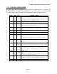
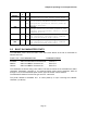
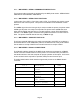
The table below lists the Serial Interface signals and pinouts on the DB25S female
connector.
MSP DB25S CONNECTOR
PIN #
FUNCTIONAL
DESCRIPTION
SIGNAL
NAME
1 Protective Earth
Ground
GND
2 RS232 from Host
(INPUT)
RXD
3 RS232 from Printer
(OUTPUT)
TXD
4 Request to send from
Host (INPUT)
RTS
5 Clear to send from
Printer (OUTPUT)
CTS
7 Logic common COM