
Printer User Manual

Chapter 1 Installation and Initial Power-Up
Page 9
1.4 MEMBRANE SWITCH PANEL
Four membrane switches are provided on the left side of the MSP/MPP printers for various
operator controls. The switches are labeled <SLCT>, <FEED>, <SET> and <ADVN>. The
functions performed by these switches are summarized below.
<SLCT> or <ON>
The <SLCT> or <ON> switch is used to turn printer power on.
The green <ON-Line> LED is illuminated, if printer is selected.
<FEED>
The <FEED> switch is used to advance the paper by one line.
<SET> or <OFF>
The <SET> or <OFF> switch is used to turn the printer OFF. The <Error> LED starts flashing
when set switch is pressed.
<ADVN> 0r < >
The <ADVN> or < > switch is used to advance paper by one line.
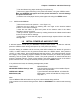
1.5 DATA CONNECTOR
The Data Connector of the MSP/MPP printer is located at the front of the printer. Figure 1.0
shows the front panel of the MSP/MPP Printer series. The serial and parallel input/output
signals of the MSP/MPP compact printers are terminated on a 25 pin, DB25S female connector.
Pin assignments and technical specifications for each type of interface are listed in Chapter 3.
1.6 POWER INPUT
The MSP/MPP compact printers receive DC power via Extech rechargeable battery pack or
through a two (2) conductor Power Input Connector located on the right side of the printer.
NOTE: The printer must be operated with the battery installed when the
Power Adapter is used. Failure to do so will invalidate the warranty.
1.6.1 AC POWER ADAPTER
A wall mount UL listed power adapter is provided to operate the printer. The AC Power
Adapter plugs directly into an AC power outlet while it's mating DC plug, on a 6 ft
extension, connects to the printer. The center pin is the positive DC input, while the
body of the connector is logic common or DC negative input.
The AC Power Adapter is internally fused and it's output is rated at 9 VDC/1.0A for
MSP II printer series and 9VDC/2.0A for MSP III. The Power adapter AC input is
available for either 110 VAC or 220 VAC.