User's Guide Extech EX845 True RMS 1000 Amp Clamp Meter with Bluetooth SEND Patented
Introduction Congratulations on your purchase of the Extech EX845 CAT IV True RMS 1000A Clamp Meter. This meter is supplied in the Meterlink kit and includes a Bluetooth module designed for use with the Flir T/B200, T/B300, T/B360, T/B400 or i/b60 cameras. The combination of a clamp meter and an IR camera is used for electrical power measurement, analysis and documentation.
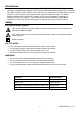
CAUTIONS Improper use of this meter can cause damage, shock, injury or death. Read and understand this user manual before operating the meter. Always remove the test leads before replacing the battery or fuses. Inspect the condition of the test leads and the meter itself for any damage before operating the meter. Repair or replace any damage before use. Use great care when making measurements if the voltages are greater than 25VAC rms or 35VDC. These voltages are considered a shock hazard.
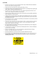
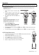
Description Meter Description 1 1. Current clamp 2. Clamp opening trigger 3. Data Hold Button 11 4. Mode 5. Peak 2 6. Range 7. DCA Zero SEND 12 8. MIN/MAX 13 9. Backlit LCD Display 10. Test lead input jacks 3 11. IR thermometer and laser pointer (rear) 5 12. Bluetooth SEND/Backlight Button 13. Laser pointer button 6 14.
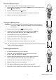
Operation NOTES: Read and understand all Warning and Caution statements in this operation manual prior to using this meter. Set the function select switch to the OFF position when the meter is not in use. AC Current Measurements WARNING: Ensure that the test leads are disconnected from the meter before making current clamp measurements. 1. Set the Function switch to the AAC or ADC range 2. Press the trigger to open the jaw. Fully enclose only one conductor.
Resistance Measurements Note: Remove power before making resistance measurements 1. Insert the black test lead into the negative COM terminal and the red test lead into the positive terminal. 2. Set the function switch to the position. 3. Touch the test probe tips across the circuit or component under test. 4. Read the resistance on the LCD display. Capacitance Measurements WARNING: To avoid electric shock, discharge the capacitor under test before measuring.
Type K Temperature Measurements 1. Set the function switch to the K Temp position. 2. Insert the Temperature Probe into the negative COM and the positive TEMP jacks, observing polarity. 3. Touch the Temperature Probe tip to the device under test. Continue to touch the part under test with the probe until the reading stabilizes. 4. Read the temperature on the display. The digital reading will indicate the proper decimal point and value.
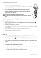
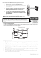
Non-Contact InfraRed Temperature Measurements 1. Set the function switch to the IR Temp position. 2. Aim the infrared sensor (rear of the meter) at the surface to be measured. 3. Press the button in the center of the rotary function switch to turn on the laser pointer and identify the surface spot to be measured. 4. The area of the surface to be measured must be larger than the spot size as determined by the distance to spot size specification. 5. Read the temperature in the display.
Data Hold To freeze the LCD reading, press the HOLD button. While data hold is active, the HOLD icon appears on the LCD. Press the HOLD button again to return to normal operation. Peak Hold The Peak Hold function captures the peak AC or DC voltage or current. The meter can capture negative or positive peaks as fast as 1 millisecond in duration. 1. Turn the function switch to the A or V position. 2. Use the MODE button to select AC or DC 3. Allow time for the display to stabilize. 4.
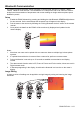
Bluetooth Communication The meter includes a Bluetooth module designed to communicate with the Flir T/B200, T/B300, T/B360, T/B400 or i/b60 cameras. The combination of a clamp meter and an IR camera is used for analysis and documentation of temperature and current readings on single and three phase power distribution panels. Setup 1. Enable the EX845 bluetooth by pressing and holding the side Bluetooth SEND/Backlight button for two seconds. On the second beep the bluetooth icon will appear in the display.
T/B200, 300, 360, 400 Image Edit 1. Entering the camera Preview mode (single press of the image store button). 2. In Preview mode real time data is no longer streamed to the image but it is displayed in a preview box. 3. The data in the box can be applied to the image by pressing the EX845 Bluetooth SEND/Backlight button or the ADD button in the camera’s preview box. 4. Data applied to the image in this way will be enumerated. i/B60 Image Edit 1. Press the trigger to store the image 2.
Maintenance WARNING: To avoid electrical shock, disconnect the meter from any circuit, remove the test leads from the input terminals, and turn OFF the meter before opening the case. Do not operate the meter with an open case. Cleaning and Storage Periodically wipe the case with a damp cloth and mild detergent; do not use abrasives or solvents. If the meter is not to be used for 60 days or more, remove the battery and store it separately. Battery Replacement 1.
Specifications Function Range & Resolution AC Current 400.0 AAC ± (2.5% + 8d) 1000 AAC ± (2.8% + 5d) 50/60 Hz DC Current Accuracy (% of reading + digits) 400.0 ADC ± (2.5% + 5d) 1000 ADC ± (2.8% + 5d) 400.0 mVAC ± (1.0% + 10d) AC Voltage 4.000 VAC 50/60Hz 40.00 VAC ± (1.5% + 5d) 400.0 VAC 1000 VAC ± (2.0% + 5d) 400.0 mVDC ± (0.8% + 2d) 4.000 VDC DC Voltage 40.00 VDC ± (1.5% + 2d) 400.0 VDC 1000 VDC ± (2.0% + 2d) 400.0 ± (1.0% + 4d) 4.000k Resistance ± (1.5% + 2d) 40.
Function Range and Resolution o -4 to 1400 F Temperature (type-K) ± (3%rdg + 9 F) o o -20 to 760 C Temp (IR) Clamp jaw opening Display Continuity check Diode test Low Battery indication Over-range indication Measurement rate Bluetooth range PEAK Thermocouple sensor IR Spectral response IR Emissivity IR distance ratio Input Impedance AC bandwidth AC response Crest Factor Operating Temperature Storage Temperature Operating Humidity Storage Humidity Operating Altitude Battery Auto power OFF Dimension