User Manual Extech EX830 True RMS 1000 Amp Clamp Meter with IR Thermometer Additional User Manual Translations available at www.extech.
Introduction Congratulations on your purchase of the Extech EX830 True RMS 1000A Clamp Meter. This meter measures AC/DC Voltage, AC/DC Current, Resistance, Capacitance, Frequency, Diode Test, Continuity, Type k thermocouple thermometer plus Non-Contact IR Temperature. This device is shipped fully tested and calibrated and, with proper use, will provide years of reliable service. Please visit our website (www.extech.
CAUTIONS • Improper use of this meter can cause damage, shock, injury or death. Read and understand this user manual before operating the meter. • For all measurements, always use approved measurement category (CAT) voltage and current rated test leads, test probes, and adapters. Do not exceed the CAT rating of the lowest rated test lead, probe, adaptor, or other product accessory. • Always remove the test leads before replacing the battery or fuses.
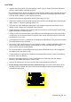
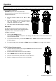
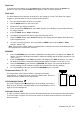
Description Meter Description 1. Current clamp 2. Clamp opening trigger 3. Data hold button 4. Peak 5. Range 6. Backlit LCD 7. Test lead input jacks 8. Mode/DC zero 9. MAX/MIN 10. Function switch 11. Laser pointer button 12. Backlight button 13.
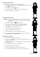
Operation NOTES: Read and understand all Warning and Caution statements in this operation manual prior to using this meter. Set the function select switch to the OFF position when the meter is not in use. Current Measurements WARNING: Ensure that the test leads are disconnected from the meter before making current clamp measurements. 1. Set the Function switch to the AAC or ADC range 2. Press the trigger to open the jaw. Fully enclose only one conductor.
Resistance Measurements Note: Remove power before making resistance measurements 1. Insert the black test lead into the negative COM terminal and the red test lead into the Ω positive terminal. 2. Set the function switch to the Ω position. 3. Touch the test probe tips across the circuit or component under test. 4. Read the resistance on the LCD display. Capacitance Measurements WARNING: To avoid electric shock, discharge the capacitor under test before measuring.
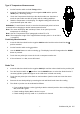
Type K Temperature Measurements 1. Set the function switch to the K Temp position. 2. Insert the Temperature Probe into the negative COM and the positive TEMP jacks, observing polarity. 3. Touch the Temperature Probe tip to the device under test. Continue to touch the part under test with the probe until the reading stabilizes. 4. Read the temperature on the display. The digital reading will indicate the proper decimal point and value.
Non-Contact InfraRed Temperature Measurements 1. Set the function switch to the IR Temp position. 2. Aim the infrared sensor (rear of the meter) at the surface to be measured. 3. Press the button in the center of the rotary function switch to turn on the laser pointer and identify the surface spot to be measured. 4. The area of the surface to be measured must be larger than the spot size as determined by the distance to spot size specification. 5. Read the temperature in the display.
Data Hold To freeze the LCD reading, press the HOLD button. While data hold is active, the HOLD icon appears on the LCD. Press the HOLD button again to return to normal operation. Peak Hold The Peak Hold function captures the peak AC or DC voltage or current. The meter can capture negative or positive peaks as fast as 1 millisecond in duration. 1. Turn the function switch to the A or V position. 2. Use the MODE button to select AC or DC 3. Allow time for the display to stabilize. 4.
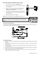
Maintenance WARNING: To avoid electrical shock, disconnect the meter from any circuit, remove the test leads from the input terminals, and turn OFF the meter before opening the case. Do not operate the meter with an open case. Cleaning and Storage Periodically wipe the case with a damp cloth and mild detergent; do not use abrasives or solvents. If the meter is not to be used for 60 days or more, remove the battery and store it separately. Battery Replacement 1.
Specifications Function Range & Resolution AC Current 400.0 AAC Accuracy (% of reading + digits) ± (2.5% + 8d) 1000 AAC ± (2.8% + 5d) 400.0 ADC ± (2.5% + 5d) 1000 ADC ± (2.8% + 5d) 400.0 mVAC ± (1.0% + 10d) 50/60 Hz DC Current AC Voltage 4.000 VAC 50/60Hz 40.00 VAC ± (1.5% + 5d) 400.0 VAC 600 VAC ± (2.0% + 5d) 400.0 mVDC ± (0.8% + 2d) 4.000 VDC DC Voltage 40.00 VDC ± (1.5% + 2d) 400.0 VDC 600 VDC ± (2.0% + 2d) 400.0Ω ± (1.0% + 4d) 4.000kΩ Resistance ± (1.5% + 2d) 40.
Function Range and Resolution Temperature (type-K) Temp (IR) Clamp jaw opening Display Continuity check Diode test Low Battery indication Over-range indication Measurement rate PEAK Thermocouple sensor IR Spectral response IR Emissivity IR distance ratio Input Impedance AC bandwidth AC response Crest Factor Operating Temperature Storage Temperature Operating Humidity Storage Humidity Operating Altitude Battery Auto power OFF Dimensions & Weight Safety Patent notice Accuracy (% of reading + digits) o