User’s Guide Shop online at omega.com ® e-mail: info@omega.com For latest product manuals: omegamanual.
OMEGAnet ® Online Service omega.com Internet e-mail info@omega.com Servicing North America: U.S.A.: ISO 9001 Certified Canada: Omega Engineering, Inc., One Omega Drive, P.O. Box 4047 Stamford, CT 06907-0047 Toll-Free: 1-800-826-6342 Tel: (203) 359-1660 FAX: (203) 359-7700 e-mail: info@omega.com 976 Bergar Laval (Quebec), H7L 5A1 Canada Toll-Free: 1-800-826-6342 FAX: (514) 856-6886 TEL: (514) 856-6928 e-mail: info@omega.ca For immediate technical or application assistance: U.S.A.
Introduction Congratulations on your purchase of the Extech EX830 True RMS 1000A Clamp Meter. This meter measures AC/DC Voltage, AC/DC Current, Resistance, Capacitance, Frequency, Duty Cycle, Diode Test, Continuity, Type k thermocouple thermometer plus Non-Contact IR Temperature. Proper use and care of this meter will provide many years of reliable service.
CAUTIONS • Improper use of this meter can cause damage, shock, injury or death. Read and understand this user manual before operating the meter. • Always remove the test leads before replacing the battery or fuses. • Inspect the condition of the test leads and the meter itself for any damage before operating the meter. Repair or replace any damage before use. • Use great care when making measurements if the voltages are greater than 25VAC rms or 35VDC. These voltages are considered a shock hazard.
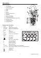
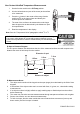
Description Meter Description 1. Current clamp 2. Clamp opening trigger 3. Data Hold Button 4. Mode 5. Peak 6. Range 7. DCA Zero (EX830 only) 8. MIN/MAX 9. Backlit LCD Display 10. Test lead input jacks 11. IR thermometer and laser pointer (rear) 12. Backlight Button 13. Laser pointer button 14.
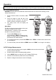
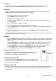
Operation NOTES: Read and understand all Warning and Caution statements in this operation manual prior to using this meter. Set the function select switch to the OFF position when the meter is not in use. AC Current Measurements WARNING: Ensure that the test leads are disconnected from the meter before making current clamp measurements. 1. Set the Function switch to the AAC or ADC range 2. Press the trigger to open the jaw. Fully enclose only one conductor.
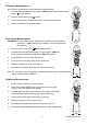
Resistance Measurements Note: Remove power before making resistance measurements 1. Insert the black test lead into the negative COM terminal and the red test lead into the Ω positive terminal. 2. Set the function switch to the Ω position. 3. Touch the test probe tips across the circuit or component under test. 4. Read the resistance on the LCD display. Capacitance Measurements WARNING: To avoid electric shock, discharge the capacitor under test before measuring.
Type K Temperature Measurements 1. Set the function switch to the K Temp position. 2. Insert the Temperature Probe into the negative COM and the positive TEMP jacks, observing polarity. 3. Touch the Temperature Probe tip to the device under test. Continue to touch the part under test with the probe until the reading stabilizes. 4. Read the temperature on the display. The digital reading will indicate the proper decimal point and value.
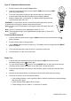
Non-Contact InfraRed Temperature Measurements 1. Set the function switch to the IR Temp position. 2. Aim the infrared sensor (rear of the meter) at the surface to be measured. 3. Press the button in the center of the rotary function switch to turn on the laser pointer and identify the surface spot to be measured. 4. The area of the surface to be measured must be larger than the spot size as determined by the distance to spot size specification. 5. Read the temperature in the display.
Data Hold To freeze the LCD reading, press the HOLD button. While data hold is active, the HOLD icon appears on the LCD. Press the HOLD button again to return to normal operation. Peak Hold The Peak Hold function captures the peak AC or DC voltage or current. The meter can capture negative or positive peaks as fast as 1 millisecond in duration. 1. Turn the function switch to the A or V position. 2. Use the MODE button to select AC or DC 3. Allow time for the display to stabilize. 4.
Maintenance WARNING: To avoid electrical shock, disconnect the meter from any circuit, remove the test leads from the input terminals, and turn OFF the meter before opening the case. Do not operate the meter with an open case. Cleaning and Storage Periodically wipe the case with a damp cloth and mild detergent; do not use abrasives or solvents. If the meter is not to be used for 60 days or more, remove the battery and store it separately. Battery Replacement 1.
Specifications Function Range & Resolution AC Current 400.0 AAC ± (2.5% + 8d) 1000 AAC ± (2.8% + 5d) 400.0 ADC ± (2.5% + 5d) 1000 ADC ± (2.8% + 5d) 400.0 mVAC ± (1.0% + 10d) 50/60 Hz DC Current AC Voltage 4.000 VAC 50/60Hz 40.00 VAC Accuracy (% of reading + digits) ± (1.5% + 5d) 400.0 VAC 600 VAC ± (2.0% + 5d) 400.0 mVDC ± (0.8% + 2d) 4.000 VDC DC Voltage ± (1.5% + 2d) 40.00 VDC 400.0 VDC 600 VDC ± (2.0% + 2d) 400.0Ω ± (1.0% + 4d) 4.000kΩ Resistance ± (1.5% + 2d) 40.
Function Temperature (type-K) Temp (IR) Range and Resolution Accuracy (% of reading + digits) o o -4 to 1400 F ± (3%rdg + 9 F) o o -20 to 760 C ± (3%rdg + 5 C) -58 to -4°F ± 9 °F -4 to 518°F ±2.0% reading or ± 4°F whichever is > -50 to -20°C ±5°C -20 to 270°C ±2.0% reading or ±2°C whichever is > Clamp jaw opening Display Continuity check Diode test 43mm (1.7") approx. 3-3/4 digits (4000 counts) backlit LCD Threshold 40Ω; Test current < 0.5mA Test current of 0.
WARRANTY/DISCLAIMER OMEGA ENGINEERING, INC. warrants this unit to be free of defects in materials and workmanship for a period of 13 months from date of purchase. OMEGA’s WARRANTY adds an additional one (1) month grace period to the normal one (1) year product warranty to cover handling and shipping time. This ensures that OMEGA’s customers receive maximum coverage on each product. If the unit malfunctions, it must be returned to the factory for evaluation.
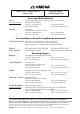
Where Do I Find Everything I Need for Process Measurement and Control? OMEGA…Of Course! Shop online at omega.