User's Guide Wireless TRMS Multimeter Model EX540
Introduction This meter measures AC/DC Voltage, AC/DC Current, Resistance, Capacitance, Frequency (electrical & electronic), Duty Cycle, Diode Test, and Continuity plus Thermocouple Temperature. It can store and recall data. It features a waterproof, rugged design for heavy duty use. This meter can transmit data wirelessly when linked to a PC. Proper use and care of this meter will provide many years of reliable service.
SAFETY INSTRUCTIONS This meter has been designed for safe use, but must be operated with caution. The rules listed below must be carefully followed for safe operation. 1.
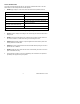
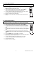
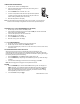
Controls and Jacks 1. 40,000 count LCD display 2. STORE() button 8 13. REL(+) button Note: Tilt stand and battery compartment are on rear of unit. Symbols and Annunciators •))) n µ m A k F M Ω Hz % AC DC ºF MAX N0.
Operating Instructions WARNING: Risk of electrocution. High-voltage circuits, both AC and DC, are very dangerous and should be measured with great care. 1. ALWAYS turn the function switch to the OFF position when the meter is not in use. 2. If “OL” appears in the display during a measurement, the value exceeds the range you have selected. Change to a higher range. DC VOLTAGE MEASUREMENTS CAUTION: Do not measure DC voltages if a motor on the circuit is being switched ON or OFF.
mV VOLTAGE MEASUREMENTS CAUTION: Do not measure mV voltages if a motor on the circuit is being switched ON or OFF. Large voltage surges may occur that can damage the meter. 1. 2. 3. 4. 5. 6. Set the function switch to the mV position. Press the MODE button to indicate “DC”or ““AC ”, or in AC range press EXIT for two seconds and chose ”AC+DC” Insert the black test lead banana plug into the negative COM jack. Insert the red test lead banana plug into the positive V jack.
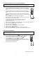
AC CURRENT (FREQUENCY, DUTY CYCLE) MEASUREMENTS CAUTION: Do not make 20A current measurements for longer than 30 seconds. Exceeding 30 seconds may cause damage to the meter and/or the test leads. 1. 2. 3. 4. 5. 6. 7. 8. 9. 10. 11. 12. 13. 14. 10. Insert the black test lead banana plug into the negative COM jack. For current measurements up to 4000µA AC, set the function switch to the µA position and insert the red test lead banana plug into the µA/mA jack.
CONTINUITY CHECK WARNING: To avoid electric shock, never measure continuity on circuits or wires that have voltage on them. 1. 2. 3. 4. 5. Set the function switch to the Ω CAP position. Insert the black lead banana plug into the negative COM jack. Insert the red test lead banana plug into the positive Ω jack. Press the MODE button to indicate“ "and “Ω” on the display Touch the test probe tips to the circuit or wire you wish to check.
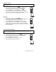
TEMPERATURE MEASUREMENTS 1. Set the function switch to the Temp position. 2. Insert the Temperature Probe into the input jacks, making sure to observe the correct polarity. 3. Press the MODE button to indicate “ºF” or “ºC” 4. Touch the Temperature Probe head to the part whose temperature you wish to measure. Keep the probe touching the part under test until the reading stabilizes (about 30 seconds). 5. Read the temperature in the display.
RELATIVE MODE The relative measurement feature allows you to make measurements relative to a stored reference value. A reference voltage, current, etc. can be stored and measurements made in comparison to that value. The displayed value is the difference between the reference value and the measured value. 1. 2. 3. 4. 5. Perform the measurement as described in the operating instructions. Press the REL button to store the reading in the display and the "▲" indicator will appear on the display.
DATA STORAGE RECALL 1. Press STORE button for two seconds to enter into RECALL function. 2. On the left upper aux display will show XXXX, which is the current storage location. The right aux display will show XXXX, which is the number of storage locations currently used. 3. Press the + or — button to select the storage location. The value in that location will be indicated in the main display. 4. Press the PEAKHOLD button once to continuously scan data from 0000 to XXXX. Press again then scan again. 5.
Maintenance WARNING: To avoid electric shock, disconnect the test leads from any source of voltage before removing the back cover or the battery or fuse covers. WARNING: To avoid electric shock, do not operate your meter until the battery and fuse covers are in place and fastened securely. This MultiMeter is designed to provide years of dependable service, if the following care instructions are performed: 1. KEEP THE METER DRY. If it gets wet, wipe it off. 2. USE AND STORE THE METER IN NORMAL TEMPERATURES.
BATTERY INSTALLATION WARNING: To avoid electric shock, disconnect the test leads from any source of voltage before removing the battery cover. 1. Turn power off and disconnect the test leads from the meter. 2. Open the rear battery cover by removing two screws (B) using a Phillips head screwdriver. 3. Insert the battery into battery holder, observing the correct polarity. 4. Put the battery cover back in place. Secure with the screws. 5.
REPLACING THE FUSES WARNING: To avoid electric shock, disconnect the test leads from any source of voltage before removing the meter cover. 1. Disconnect the test leads from the meter. 2. Remove the protective rubber holster. 3. Remove the battery cover (two “B” screws) and the battery. 4. Remove the six “A” screws securing the rear cover. 5. Gently remove the old fuse and install the new fuse into the holder. 6. Always use a fuse of the proper size and value (0.
Specifications Function DC Voltage Range 400mV 4V 40V 400V 1000V Resolution 0.01mV 0.0001V 0.001V 0.01V 0.1V Accuracy ±(0.06% reading + 2 digits) ±(0.1% reading + 2 digits) AC Voltage 400mV 0.01mV ±(1.0% reading + 4digits) (AC+DC) 4V 0.0001V 50 to 1000Hz 40V 0.001V ±(1.0% reading + 3digits) 400V 0.01V 1000V 0.1V All AC voltage ranges are specified from 5% of range to 100% of range DC Current 400μA 0.01μA 4000μA 0.1μA ±(1.0% reading + 3 digits) 40mA 0.001mA 400mA 0.01mA 10A 0.
Function Resistance Capacitance Frequency (electronic) Frequency (electrical) Duty Cycle Range Resolution 400Ω 0.01Ω 4kΩ 0.0001kΩ 40kΩ 0.001kΩ 400kΩ 0.01kΩ 4MΩ 0.001MΩ 40MΩ 40nF 400nF 0.001MΩ 0.001nF 0.01nF 4μF 0.0001μF 40μF 0.001μF Accuracy ±(0.3% reading + 9 digits) ±(0.3% reading + 4 digits) ±(2.0% reading + 10 digits) ±(3.5% reading + 40 digits) ±(3.5% reading + 10 digits) 400μF 0.01μF 4000µF 0.1µF ±(5% reading + 10 digits) 40mF 0.001mF 40Hz 0.001Hz 400Hz 0.01Hz 4kHz 0.
Enclosure Shock (Drop Test) Diode Test Double molded, waterproof (IP67) 2 meters (6.5 feet) Test current of 0.9mA maximum, open circuit voltage 2.8V DC typical Storage capacity 9999 records RF transmit distance 10 meters (approx) Transmitter Frequency 915MHz Continuity Check Audible signal will sound if the resistance is less than 35Ω (approx.), test current <0.