User's Guide Autoranging True RMS Multimeter Extech EX505
Introduction Congratulations on your purchase of the Extech EX505 True RMS Autoranging Multimeter. This meter measures AC/DC Voltage, AC/DC Current, Resistance, Capacitance, Frequency, Diode Test, and Continuity plus Thermocouple Temperature. It features a waterproof, rugged design for heavy duty use This meter is shipped fully tested and calibrated and, with proper use, will provide years of reliable service.
CAUTIONS Improper use of this meter can cause damage, shock, injury or death. Read and understand this user manual before operating the meter. Always remove the test leads before replacing the battery or fuses. Inspect the condition of the test leads and the meter itself for any damage before operating the meter. Repair or replace any damage before use. Use great care when making measurements if the voltages are greater than 25VAC rms or 35VDC. These voltages are considered a shock hazard.
SAFETY INSTRUCTIONS This meter has been designed for safe use, but must be operated with caution. The rules listed below must be carefully followed for safe operation. 1. NEVER apply voltage or current to the meter that exceeds the specified maximum: Input Protection Limits Function Maximum Input V DC or V AC 1000VDC/AC rms mA AC/DC 400mA AC/DC A AC/DC 10A AC/DC (20A for 30 sec) Frequency, Resistance, Capacitance, Diode Test, Continuity, Temperature 600VDC/AC rms 2.
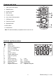
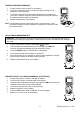
Controls and Jacks 1. 4,000 count LCD display 2. RANGE button 3. Hz and % button 4. Mode button 5. Function switch 6. mA, µA and 10A input jacks 7. COM input jack 8. Positive input jack 9. Backlight button 10. REL button 11. HOLD button Note: Tilt stand and battery compartment are on rear of unit.
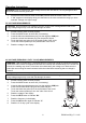
Operating Instructions WARNING: Risk of electrocution. High-voltage circuits, both AC and DC, are very dangerous and should be measured with great care. 1. ALWAYS turn the function switch to the OFF position when the meter is not in use. 2. If “OL” appears in the display during a measurement, the value exceeds the range you have selected. Change to a higher range. DC VOLTAGE MEASUREMENTS CAUTION: Do not measure DC voltages if a motor on the circuit is being switched ON or OFF.
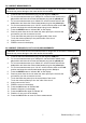
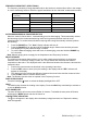
DC CURRENT MEASUREMENTS CAUTION: Do not make 20A current measurements for longer than 30 seconds. Exceeding 30 seconds may cause damage to the meter and/or the test leads. 1. 2. 3. 4. 5. 6. 7. 8. 9. Insert the black test lead banana plug into the negative COM jack. For current measurements up to 4000µA DC, set the function switch to the µA position and insert the red test lead banana plug into the µA/mA jack.
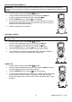
RESISTANCE MEASUREMENTS WARNING: To avoid electric shock, disconnect power to the unit under test and discharge all capacitors before taking any resistance measurements. Remove the batteries and unplug the line cords. 1. 2. 3. 4. 5. Set the function switch to the ΩCAP position. Insert the black test lead banana plug into the negative COM jack. Insert the red test lead banana plug into the positive jack. Press the MODE button to indicate “"on the display.
TEMPERATURE MEASUREMENTS 1. 2. 3. 4. Set the function switch to the ºF or ºC position. Insert the Temperature Probe into the input jacks, making sure to observe the correct polarity. Touch the Temperature Probe head to the part whose temperature you wish to measure. Keep the probe touching the part under test until the reading stabilizes (about 30 seconds). Read the temperature in the display. Note: The temperature probe is fitted with a type K mini connector.
FREQUENCY SENSITIVITY (ELECTRICAL) The frequency sensitivity is range dependent when the function is selected from while in the voltage or current measuring function. Below are typical sensitivities for the “electrical” measurement modes. Range ( DC/AC ) 4V Sensitivity Frequency width ≥1.
Maintenance WARNING: To avoid electric shock, disconnect the test leads from any source of voltage before removing the back cover or the battery or fuse covers. WARNING: To avoid electric shock, do not operate your meter until the battery and fuse covers are in place and fastened securely. This MultiMeter is designed to provide years of dependable service, if the following care instructions are performed: 1. KEEP THE METER DRY. If it gets wet, wipe it off. 2.
BATTERY INSTALLATION WARNING: To avoid electric shock, disconnect the test leads from any source of voltage before removing the battery cover. 1. 2. 3. 4. 5. Turn power off and disconnect the test leads from the meter. Open the rear battery cover by removing two screws (B) using a Phillips head screwdriver. Insert the battery into battery holder, observing the correct polarity. Put the battery cover back in place. Secure with the screws.
Specifications Function DC Voltage AC Voltage DC Current AC Current Range 400mV Resolution 0.1mV 4V 40V 400V 1000V 0.001V 0.01V 0.1V 1V (1.5% reading + 10 digits) 400mV 0.1mV (2.0% reading + 10 digits) 4V 40V 400V 1000V 0.001V 0.01V 0.1V 1V 400A 0.1A 4000A 40mA 400mA 10A 1A 0.01mA 0.1mA 0.01A 400A 0.1A 4000A 40mA 400mA 10A 1A 0.01mA 0.1mA 0.01A o Accuracy (0.5% reading + 2 digits) (1.2% reading + 2 digits) (2.0% reading + 5 digits) (2.5% reading + 5 digits) (1.
Function Resistance Capacitance Frequency Duty Cycle Range Resolution 400 0.1 (1.2% reading + 4 digits) Accuracy 4k 0.001k (1.0% reading + 2 digits) 40k 0.01k 400k 0.1k 4M 0.001M 40M 4nF 0.01M 0.001nF (2.0% reading + 3 digits) 40nF 0.01nF (5.0% reading + 7 digits) 400nF 0.1nF 4F 0.001F 40F 0.01F (1.2% reading + 2 digits) (5.0% reading + 0.5nF) (3.0% reading + 5 digits) 100F 0.1F (5% reading + 5 digits) 5.999Hz 0.001Hz (1.5% reading + 1 digits) 59.
Enclosure Shock (Drop Test) Diode Test Continuity Check Double molded, waterproof (IP67) 2 meters (6.5 feet) Test current of 0.3mA typical, open circuit voltage 1.5V DC typical Audible signal will sound if the resistance is less than 100 (approx.), test current <0.3mA Temperature Sensor Requires type K thermocouple Input Impedance 10MΩ VDC & 10MΩ VAC AC Response True rms ACV Bandwidth 40Hz to 400Hz Crest Factor ≤3 at full scale up to 500V, decreasing linearly to ≤1.