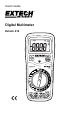
User's Guide Digital Multimeter Extech 410
Introduction Congratulations on your purchase of the Extech EX410 Multimeter. This meter measures AC/DC Voltage, AC/DC Current, Resistance, Diode Test, and Continuity plus Thermocouple Temperature. This device is shipped fully tested and calibrated and, with proper use, will provide years of reliable service. Please visit our website (www.extech.com) to check for the latest version of this User Guide, Product Updates, and Customer Support.
CAUTIONS Improper use of this meter can cause damage, shock, injury or death. Read and understand this user manual before operating the meter. Always remove the test leads before replacing the battery or fuses. Inspect the condition of the test leads and the meter itself for any damage before operating the meter. Repair or replace any damage before use. Use great care when making measurements if the voltages are greater than 25VAC rms or 35VDC. These voltages are considered a shock hazard.
OVERVOLTAGE CATEGORY III This meter meets the IEC 61010-1-2001 standard for OVERVOLTAGE CATEGORY III. Cat III meters are protected against overvoltage transients in fixed installation at the distribution level. Examples include switches in the fixed installation and some equipment for industrial use with permanent connection to the fixed installation. SAFETY INSTRUCTIONS This meter has been designed for safe use, but must be operated with caution.
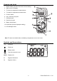
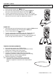
Controls and Jacks 1. Rubber holster (must be removed to access battery) 2. 2000 count LCD display 3. °F button for temperature measurements 4. °C button for temperature measurements 5. Function switch 6. mA, uA and A input jacks 7. COM input jack 8. Positive input jack 9. Battery check button 10. Hold button (freezes displayed reading) 11. LCD backlight button Note: Tilt stand, test lead holders, and battery compartment are on rear of unit.
Operating Instructions WARNING: Risk of electrocution. High-voltage circuits, both AC and DC, are very dangerous and should be measured with great care. 1. ALWAYS turn the function switch to the OFF position when the meter is not in use. 2. If “1” appears in the display during a measurement, the value exceeds the range you have selected. Change to a higher range. NOTE: On some low AC and DC voltage ranges, with the test leads not connected to a device, the display may show a random, changing reading.
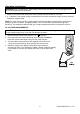
AC VOLTAGE MEASUREMENTS WARNING: Risk of Electrocution. The probe tips may not be long enough to contact the live parts inside some 240V outlets for appliances because the contacts are recessed deep in the outlets. As a result, the reading may show 0 volts when the outlet actually has voltage on it. Make sure the probe tips are touching the metal contacts inside the outlet before assuming that no voltage is present. CAUTION: Do not measure AC voltages if a motor on the circuit is being switched ON or OFF.
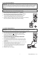
AC CURRENT MEASUREMENTS CAUTION: Do not make current measurements on the 20A scale for longer than 30 seconds. Exceeding 30 seconds may cause damage to the meter and/or the test leads. 1. Insert the black test lead banana plug into the negative COM jack. 2. For current measurements up to 200mA AC, set the function switch to the highest 200mA AC ( ) position and insert the red test lead banana plug into the mA jack. 3.
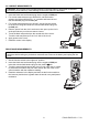
CONTINUITY CHECK WARNING: To avoid electric shock, never measure continuity on circuits or wires that have voltage on them. 1. Set the function switch to the position. 2. Insert the black lead banana plug into the negative COM jack. Insert the red test lead banana plug into the positive jack. 3. Touch the test probe tips to the circuit or wire you wish to check. 4. If the resistance is less than approximately 150, the audible signal will sound. If the circuit is open, the display will indicate “1”.
DISPLAY BACKLIGHT Press and hold the 15 seconds. button to turn on the display backlight function. The backlight will automatically turn off after BATTERY CHECK The CHECK function tests the condition of the 9V battery. Set the function switch to the 200VDC range and press the CHECK button. If the reading is less than 8.5, battery replacement is recommended. HOLD The hold function freezes the reading in the display. Press the HOLD key momentarily to activate or to exit the hold function.
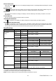
General Specifications Diode Test Test current of 1mA maximum, open circuit voltage 2.8V DC typical Continuity Check Audible signal when resistance is less than approximately 150 Input Impedance 10MΩ AC Response Average responding ACV Bandwidth 50Hz to 1kHz DCA voltage drop 200mV Display 3 ½ digit, 2000 count LCD, 0.
Maintenance WARNING: To avoid electrical shock, disconnect the meter from any circuit, remove the test leads from the input terminals, and turn OFF the meter before opening the case. Do not operate the meter with an open case. This MultiMeter is designed to provide years of dependable service, if the following care instructions are performed: 1. KEEP THE METER DRY. If it gets wet, wipe it off. 2. USE AND STORE THE METER IN NORMAL TEMPERATURES.
REPLACING THE FUSES WARNING: To avoid electrical shock, disconnect the meter from any circuit, remove the test leads from the input terminals, and turn OFF the meter before opening the case. Do not operate the meter with an open case. 1. Disconnect the test leads from the meter. 2. Remove the protective rubber holster. 3. Remove the battery cover (two “B” screws) and the battery. 4. Remove the four “A” screws securing the rear cover. 5.