USER MANUAL Mini Multimeter with Non-Contact Voltage Detector (NCV) Model EX330
Introduction Congratulations on your purchase of the Extech EX330 Meter. The EX330 offers AC/DC Voltage, AC/DC Current, Resistance, Diode, Continuity, non-contact Voltage Detection, Capacitance, Frequency, Duty Cycle, and Temperature (Type K) functions. Proper use and care of this meter will provide many years of reliable service. For copies of this user manual in other languages please visit the www.extech.com website.
CAUTIONS Improper use of this meter can cause damage, shock, injury or death. Read and understand this user manual before operating the meter. Always remove the test leads before replacing the battery or fuses. Inspect the condition of the test leads and the meter itself for any damage before operating the meter. Repair or replace any damage before use. Use great care when making measurements if the voltages are greater than 25VAC rms or 35VDC. These voltages are considered a shock hazard.
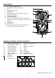
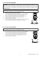
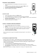
Description 1. 2. 3. 4. 5. 6. 7. 8. 9. 10. AC Voltage Detector Sensor AC Voltage Detector indicator light LCD RELATIVE push-button MODE button Non-contact AC Voltage Detector test button Rotary function dial 10 ampere test lead jack COM test lead jack Test lead jack for voltage, milli-amp, micro-amp, resistance, capacitance, frequency, and temperature functions 11. RANGE button 12. HOLD button 13.
Operating Instructions WARNING: Risk of electrocution. High-voltage circuits, both AC and DC, are very dangerous and should be measured with great care. 1. ALWAYS turn the function switch to the OFF position when the meter is not in use. 2. Press the HOLD button to freeze a displayed reading NOTE: On some low AC and DC voltage ranges, with the test leads not connected to a device, the display may show a random, changing reading. This is normal and is caused by the high-input sensitivity.
AC VOLTAGE MEASUREMENTS WARNING: Risk of Electrocution. The probe tips may not be long enough to contact the live parts inside some 240V outlets for appliances because the contacts are recessed deep in the outlets. As a result, the reading may show 0 volts when the outlet actually has voltage on it. Make sure the probe tips are touching the metal contacts inside the outlet before assuming that no voltage is present. CAUTION: Do not measure AC voltages if a motor on the circuit is being switched ON or OFF.
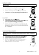
AC / DC CURRENT MEASUREMENTS CAUTION: Do not make current measurements at 10 Amps for longer than 30 seconds. Exceeding 30 seconds may cause damage to the meter and/or the test leads. 1. 2. 3. 4. 5. 6. 7. 8. 9. Insert the black test lead banana plug into the negative COM jack.
CONTINUITY CHECK WARNING: To avoid electric shock, never measure continuity on circuits or wires that have voltage on them. 1. 2. 3. 4. 5. 6. Set the function switch to the position. Insert the black lead banana plug into the negative COM jack. Insert the red test lead banana plug into the positive jack. Use the MODE button to view the icon on the display. Touch the test probe tips to the circuit or wire you wish to check. If the resistance is less than approximately 35, the audible signal will sound.
FREQUENCY MEASUREMENTS 1. 2. 3. 4. Use the MODE button to view the Hz unit of measure on the LCD display. Insert the black test lead banana plug into the negative COM jack and the red test lead banana plug into the positive Hz jack. Touch the test probe tips to the circuit under test. Read the frequency on the display. % DUTY CYCLE 1. 2. 3. 4. 5. Set the rotary function switch to the Hz/% position. Use the MODE button to view the % unit of measure on the LCD display.
RELATIVE MODE The relative measurement feature allows you to make measurements relative to a stored reference value. A reference voltage, current, etc. can be stored so that subsequent measurements can be made in comparison to that value. The displayed value is the difference between the reference value and the measured value. 1. 2. 3. Perform the measurement as described in the operating instructions. Press the REL button to store the reading (the REL indicator will appear on the display).
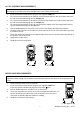
BATTERY INSTALLATION and LOW BATTERY INDICATION WARNING: To avoid electric shock, disconnect the test leads from any source of voltage before removing the battery cover. LOW BATTERY INDICATION The icon will appear in the lower left-hand corner of the display when the battery voltage becomes low. Replace the batteries when this appears. BATTERY REPLACEMENT 1. Disconnect the test leads from the meter. 2. Remove the protective rubber holster as shown in the diagram. 3.
REPLACING THE FUSES WARNING: To avoid electric shock, disconnect the test leads from any source of voltage before removing the fuse cover. 1. Disconnect the test leads from the meter. 2. Remove the protective rubber holster as shown in the diagram. 3. Remove the Phillips head screw located on the lower back of the instrument. 4. Flip up the fuse/battery compartment cover to access the fuses. 5. Gently remove the fuse(s) and install new fuse(s) into the holder(s). 6.
Resistance Capacitance Frequency (1.2% reading + 4 digits) 400 0.1 4k 1 40k 0.01k 400k 0.1k 4M 0.001M 40M 0.01M (2.0% reading + 3 digits) 4nF 40nF 400nF 0.001nF 0.01nF 0.1nF (3.5% reading + 40 digits) 4F 0.001F 40F 0.01F (3.5% reading + 4 digits) 200F 5.000Hz 50.00Hz 500.0 Hz 5.000kHz 50.00kHz 500.0kHz 5.00MHz 10.00MHz 0.1F 0.001Hz 0.01Hz 0.1Hz 0.001kHz 0.01kHz 0.001MHz 0.01MHz 0.01MHz (1.2% reading + 2 digits) (2.5% reading + 4 digits) (3.
General Specifications Diode Test Continuity Check Temperature Sensor Input Impedance AC Bandwidth Display Overrange indication Test current: 0.3mA max., Open circuit voltage: 1.5V DC typ.