User's Guide Multimeter with IR Thermometer Extech EX230
Introduction Congratulations on your purchase of the Extech EX230 Autoranging Multimeter. This meter measures AC/DC Voltage, AC/DC Current, Resistance, Capacitance, Frequency, Duty Cycle, Diode Test, and Continuity plus non-contact InfraRed Temperature and contact thermocouple Temperature. Proper use and care of this meter will provide many years of reliable service.
CAUTIONS • Improper use of this meter can cause damage, shock, injury or death. Read and understand this user manual before operating the meter. • Always remove the test leads before replacing the battery or fuses. • Inspect the condition of the test leads and the meter itself for any damage before operating the meter. • Use great care when making measurements if the voltages are greater than 25 VAC rms or 35 VDC. These voltages are considered a shock hazard. • Warning! This is a Class A device.
SAFETY INSTRUCTIONS This meter has been designed for safe use, but must be operated with caution. The rules listed below must be carefully followed for safe operation. 1. NEVER apply voltage or current to the meter that exceeds the specified maximum: Input Protection Limits Function Maximum Input V AC/DC, Resistance, Capacitance, Frequency, Temperature, Duty Cycle, Diode Test, Continuity 600 VDC/AC rms μA or mA AC/DC 500mA fused A AC/DC 10A fused 2.
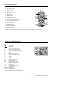
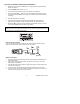
Controls and Jacks 1. IR Thermometer 2 2. Laser Pointer 1 3. 4000 count LCD 4. MAX button 3 5. MODE button 4 5 6. FUNCTION switch 8 9 7. mA, µA and 10A input jacks 10 6 8. IR Thermometer button 11 12 9. HOLD button 7 10. RANGE button 11. Positive input jack 12. COM input jack Note: Tilt stand, test lead holders, and battery compartment are on rear of unit.
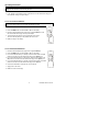
Operating Instructions WARNING: Risk of electrocution. High-voltage circuits, both AC and DC, are extremely dangerous and should be measured with great care. 1. ALWAYS turn the function switch to the OFF position when the meter is not in use. 2. If “OL” appears in the display during a measurement, the value exceeds the range you have selected. Change to a higher range. AC/DC VOLTAGE MEASUREMENTS CAUTION: Do not measure DC voltages if a motor on the circuit is being switched ON or OFF.
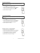
RESISTANCE MEASUREMENTS WARNING: To avoid electric shock, disconnect power to the unit under test and discharge all capacitors before taking any resistance measurements. Remove the batteries and unplug the line cords. 1. Rotate the function switch to the Ω position. 2. Press the MODE button to indicate Ω on the display. 3. Insert the black test lead banana plug into the negative COM jack. Insert the red test lead banana plug into the positive Ω jack. 4.
CONTACT TEMPERATURE MEASUREMENTS (THERMOCOUPLE PROBE) 1. Rotate the function switch to the °F or °C position. 2. Insert the temperature probe adaptor into the negative COM jack and the positive TEMP jack (the adaptor is labeled plus + and minus -) 3. Touch the temperature probe tip to a surface or leave suspended in air. 4. Read the temperature in the display. CONTINUITY CHECK WARNING: To avoid electric shock, never measure continuity on circuits or wires that have a voltage potential. 1.
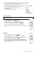
NON-CONTACT INFRARED TEMPERATURE MEASUREMENTS 1. Rotate the function switch to the IR position. The upper right four digit temperature display will switch on. 2. Press the MODE button to select °F or °C. 3. Aim the infrared sensor (top of meter) at the surface to be measured. 4. Press and Hold the IRT button to turn on the IR thermometer and laser pointer. The laser pointer identifies the surface spot to be measured and “SCAN” will flash in the display. 5. Read the temperature in the display. 6.
AUTORANGING/MANUAL RANGE SELECTION When the meter is first switched on, it automatically enters the AutoRanging mode. This automatically selects the best range for the measurements being made and is generally the best mode for most measurements. For measurement situations requiring that a range be manually selected, perform the following: 1. Press the RANGE button. The “AUTO” display indicator will turn off. 2. Press the RANGE key to step through the available ranges until the range desired is selected. 3.
Maintenance WARNING: To avoid electric shock, disconnect the test leads from any source of voltage before removing the back cover or the battery or fuse covers. WARNING: To avoid electric shock, do not operate the meter until the battery and fuse covers are in place and fastened securely. This MultiMeter is designed to provide years of dependable service, if the following care instructions are followed: 1. KEEP THE METER DRY. If it gets wet, wipe it off. 2. USE AND STORE THE METER IN NORMAL TEMPERATURES.
Specifications Function Range Resolution DC Voltage 400 mV 0.1 mV 4V 0.001V 40V 0.01V 400V 0.1V 600V 1V 400 mV 0.1 mV 4V 0.001V 40V 0.01V 400V 0.1V 600V 1V AC Voltage Accuracy ±(0.8% reading + 6 digits) ±(0.5% reading + 2 digits) ±(0.8% reading + 2 digits) ±(1.0% rdg + 6 digits) Note: All AC voltage ranges are specified from 5% of range to 100% of range DC Current 400 μA 0.1 μA 4000 μA 1 μA 40 mA 0.01 mA 400 mA 0.1 mA 4.000 0.001 A 10 A 0.01 A ±(1.
Function Range Resolution Resistance 400 Ω 0.1 Ω 4 kΩ 0.001 kΩ 40 kΩ 0.01 kΩ 400 kΩ 0.1 kΩ 4 MΩ 0.001 MΩ 40 MΩ 0.01 MΩ 40.00 nF 10 pF 400.0 nF 0.1 nF 4.000 µF 1 nF 40.00 µF 10 nF 100.0 µF 0.1 µF Capacitance Accuracy ±(0.8% reading + 5 digits) ±(0.8% reading + 2 digits) ±(2.5% reading + 8 digits) ±(5.0% reading + 7 digits) Note: Auto ranging; Input protection 600Vdc and AC rms Frequency 5.000 Hz 0.001Hz 50.00 Hz 0.01 Hz 500.0 Hz 0.1 Hz 5.000 kHz 1 Hz 50.
Enclosure Diode Test Double molded Test current of 0.9mA maximum, open circuit voltage 2.8V DC typical Continuity Threshold 20 to 100Ω, test current <1.5mA Input Impedance 10MΩ VDC/VAC AC Response Average responding ACV Bandwidth 40Hz to 1000Hz IR Spectral response 6 to 16µm IR Emissivity 0.