USER GUIDE Model DCP60 and Model DCP60‐220 Switching Mode DC Power Supplies 60V / 10A Adjustable
Introduction and Features Thank you for selecting the Extech DCP60 (110V) or DCP60‐220 (220V) Switching Power Supply. The DCP60 is highly efficient, incorporates upgraded SMPS circuitry with small form factor, benefits from an automatic cross‐over for CC and CV, has three (3) Voltage/Current presets, and can be remote controlled. The DCP60 is perfect for solving a variety of loading conditions and applications.
Safety This manual contains important safety and operation instructions for correct use of the power supply. Read through the manual and pay special attention to the markings and labels of this unit and equipment to be connected. Pay special attention to these two types of notices used in this manual: WARNING : Failure to observe this warning may cause injury to persons and damage to power supply or connected equipment.
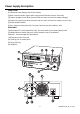
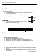
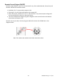
Power Supply Description FRONT PANEL (1) LED panel meter display with CC/CV Indictor (2) Rear Control Indicator (lights when using Preset/ Remote Control/ Set mode) (3) Output Voltage Control Knob (controls both the main and auxiliary output voltage) (4) Output Current Control Knob (controls both the main and auxiliary output current limit) (5) Power ON/OFF Switch (6) Aux. output terminal (max 5A); The total rated current (Aux.
Control Mode Selections There are four control modes for the power supply: NORMAL, PRESET, SET and REMOTE CONTROL modes. Slide the Mode Selection Switch (8) to the desired Mode. The power supply is factory preset to Normal Mode with maximum current level CC. Normal Mode This is the factory default mode; the power supply output Voltage and Current are controlled by the dual action gain knobs. 1. Push the knobs to toggle the coarse and fine tuning, notice the subtle changes in brightness of the related LED.
Remote Control Mode To control the output voltage and current by remote control connector (10) please refer to the section entitled Remote Control. Reset to Factory Default settings 1. 2. 3. 4.
Operation Note: The DC60 Max Output Voltage is 60VDC and the total rated current (Aux.+Main) is 10A Powering the Supply Check the rating label of the power supply and ensure that it complies with the AC mains voltage that is to be used. Connect the power supply to the AC Mains using the provided power cord. Ensure that the Mode Switch (8) is set to the Normal Mode position. The Model DCP60 requires a 110VAC power source and the DCP‐220 requires a 220V power source.
Using the control knobs The rotary encoder control knobs have fine and coarse tuning with ‘clicking’ movement. Push the knobs to toggle between coarse and fine tuning, notice the subtle changes in brightness of the related LED. Adjust the knobs to the desired values by using coarse and then fine tuning. The display will resume its normal brightness after few seconds to confirm an adjustment. Connecting the Power Supply and running a test 1. Connect the equipment under test to the power supply.
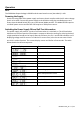
Remote Control Operation There are two methods for remotely controlling current and voltage adjustments. Current must be controlled for both methods otherwise the unit will default to CC mode. REMOTE CONTROL – METHOD 1: Using two external DC voltage sources Remote Socket Pin Assignment for external variable voltage source PIN FUNCTIONS REMARKS 1 Internal DC +5V Lower than 50mA 2 Voltage adjust 0 to 5V External VDC 3 Current adjust 0 to 5V External VDC 4 Ground 5 Output OFF Short to ground for OFF 6 N.A.
Remote Control Output ON/OFF Remote output ON/OFF control can be activated in any of the modes Normal, Preset, Set, and Remote. Review the conditions below: By default, Pin 5 is open and the output is ON. Shorting Pin 5 to Pin 4 (ground) switches the output OFF. When the output is OFF, the C.V. & C.C. LEDs will flash. The present output voltage and current setting will be shown on the panel meter.
PC Software Program Quick Start Software Installation Instructions 1. Create a new folder on the desktop of the PC, which is to be loaded with the DCP60 software. Name the folder DCP60 or any easily distinguishable name. 2. Insert the DCP60 PC Interface Software CD into the CD/DVD drive. When the Auto Play dialog box appears, select “Open folder to view files”. 3. Select all files on the CD and drag/drop or copy them into the folder that was created in Step 1. 4.
Main Interface Display The Main interface is divided into 7 panels. 1. 2. 3. 4. 5. 6. 7. Display panel: Indicates real‐time power supply information. Main Configuration and Datalogger Display panel: Use this panel to adjust general program settings and to view External Timed Programs, Internal Preset Memory data, and Datalogger information. Voltage and Current setting panel: Use this panel to set the output values and to switch the output On/Off.
Display Panel 1. 2. 3. 4. Actual Output Voltage, Current, and Power values C.V./ C.C. Mode status Setting values Output ON/OFF status Output Setting Panel 1. 2. 3. 4. Voltage Output setting Current Output setting Output ON/OFF setting SET (confirm) output values Directly type the value in the Voltage and Current fields or use the slider to set the Voltage and Current values and then press SET to confirm. Click ON or OFF to set the output status.
Setting Tab On the ‘Setting’ page, general program settings can be configured as listed below: Select the desired language. Select the PC COM Port number to which the power supply is to be connected. Set the datalogging sampling time (rate) using the slide bar. Set the output voltage upper limit (UVL) value to further safeguard low voltage applications. This sets the limits for all Tabs. Set the output current upper limit (UCL) value to further safeguard low current applications.
External Timed Program External Timed Programs are completely PC controlled. The PC automatically changes the Voltage and Current outputs (and their time duration) based on pre‐programmed settings. Click on the EXTERNAL TIMED PROGRAM tab and then double click a cell to set a value. For example (see diagram below), Step 2 Voltage, slide the bar to set the desired output level Once the Slider is active, you can use the keyboard left and right arrow keys to fine adjust the setting.
Internal Preset Memory The PC interface’s remote Preset capability simplifies the tedious process of keying in groups of entries. Since all the data are displayed at the same time on the PC monitor, the possibility of entering data incorrectly is greatly reduced. Data of different groups can be classified, stored, exported and retrieved for use at any time. Retrieved data will appear red in color if they exceed the preset voltage/current limits.
Datalogger Window 1. 2. Adjust slider to move the displayed waveform left and right Adjust slider to zoom in and out Note: Once the Slider is active, you can use your keyboard left and right arrow keys to fine adjust your setting. The graphical datalogger window is used to display output Voltage, Current, and Power over time. 17 DCP60‐en‐EU_V1.
Save, Load, and Print Data External Timed Program tab The buttons are used to Save and Load an External Timed Program or Print the current settings. If desired, add a description in the Program Description field. Click to save an External Timed Program to a CSV file. Click to open and load settings from a CSV file. Click to print the settings. Internal Preset Memory tab The buttons are used to Save and Load Internal Preset data or Print the current settings.
Software Programming Command Set (Protocol) Command line format: COMMAND...
GOCP[CR] Return value: [CR] OK[CR] =??? Input Command: SOCP[CR] Return value: OK[CR] Preset upper limit of output Current =000 [CR] Return value: OK[CR] Save Voltage and Current value into 3 PS memory locations =??? =??? (X is memory location number start from 0 to 2) Input Command: GETM[CR] Return value:
Specifications Output Variable Voltage Output Variable Current Output Voltage Regulation Load (10 to 100% Load) Model DCP60 Model DCP60‐220 Current Regulation Load (10 to 90% rated voltage) Model DCP60 Model DCP60‐220 Ripple and Noise Ripple and Noise (RMS) voltage Ripple and Noise (P‐P) voltage Current Ripple and Noise (RMS) Meter Type and Accuracy Voltage Meter Current Meter Input Input Voltage 1 to 60VDC 0 to 10ADC 50mV Line (90 to 130VAC Variation): Line (170 to 264VAC Variation): 20mV 20mV 100mA Lin
Troubleshooting OUP: Over Voltage Protection This unit has a built‐in tracking over voltage protection feature. In the event of output voltage becoming greater than the set value (see specified range from specifications table), protection will be triggered and the output power will be cut off and OUP warning appears as below. To reset the warning, switch off the unit and remove all loading. Switch the unit back on again and it should resume normal operation.