USER GUIDE Model DCP42 160W Laboratory Grade Constant Power, Switching Mode Power Supply
Table of Contents 1. INTRODUCTION AND FEATURES 4 2. SAFETY 5 3. POWER SUPPLY DESCRIPTION 6 4. CONTROL MODES 7 5. 6. 4.1 Normal Mode 7 4.2 Preset Mode 7 4.3 Set Mode 7 4.3.1 Setting the ΔV/Δt value 4.3.2 Activating the Remote Control Mode 4.3.3 Deactivating the Remote Control Mode 4.3.4 Factory Default Reset 7 8 8 8 OPERATION 9 5.1 Powering the Supply 9 5.2 Switching the Power Supply ON and Self‐Test Information 9 5.3 Using the Control knobs 9 5.
6.1 ΔV/Δt Function 10 6.1.2 Setting the DC generator voltage level 6.1.2 Setting the Δt 6.1.3 Generating Ramp‐Up or Ramp‐Down DC output cycles 10 10 10 6.2 Function A/B/C Waveform Generator 11 6.2.1 Set FUNC (A/B/C): 6.2.2 Generating Wave Form 11 11 6.3 Upper Voltage and Current Limits 12 6.4 Remote Sensing 12 6.4.1 Connection 6.4.2 Disconnection 12 12 6.5 Remote Control Operation 13 6.5.1 REMOTE CONTROL – METHOD 1: Using two external DC voltage sources 13 6.5.
1. Introduction and Features Thank you for selecting the Extech DCP42 Switching Mode Power Supply. This newly re‐designed laboratory grade power supply differs from a conventional power supply in that it can calculate and change the voltage and current limit points according to the available maximum power. Therefore the maximum limits of the voltage and current are changeable according to the rated power.
2. Safety This manual contains important safety and operation instructions for correct use of the power supply. Read through the manual and pay special attention to the markings and labels of this unit and equipment to be connected. Pay special attention to these two types of notices used in this manual: WARNING : Failure to observe this warning may cause injury to persons and damage to power supply or connected equipment.
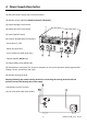
3.
4. Control Modes There are four control modes for the power supply: NORMAL, PRESET, SET, and REMOTE CONTROL modes. The power supply is factory preset to Normal Mode with maximum current level CC. 4.1 Normal Mode This is the factory default mode; the power supply output Voltage and Current are controlled by the dual action gain knobs. 1. Push the knobs to toggle the coarse and fine tuning, notice the subtle changes in brightness of the related LED. 2.
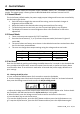
4.3.2 Activating the Remote Control Mode a. Press and hold the MENU button for 3 seconds. b. Turn the Voltage control knob until the panel meter displays “rC Set” as shown below and then press the Voltage control knob to confirm entry into the remote control mode. c. Turn the Current control knob to select remote YES or NO. d. Press the Voltage control knob to confirm and to return to the Set menu. e. Press the Menu button to exit the Set menu. f.
5. Operation Note: The DCP42 Total Output Voltage Range is 42VDC and the Total Rated Current is 0 to 10ADC 5.1 Powering the Supply Check the rating label of the power supply and ensure that it complies with the AC mains voltage that is to be used. Connect the power supply to the AC Mains using the provided power cord. 5.2 Switching the Power Supply ON and Self‐Test Information The power supply will perform a series of self‐tests when it is switched ON.
6. Supplemental Functions 6.1 ΔV/Δt Function There are 3 DC voltage generator settings (A, B, and C). Preset 1 = A Preset 2 = B Preset 3 = C ΔV a‐b (from voltage level A to voltage level B). Δt a‐b (time in seconds from voltage level A to level B, this transit time is adjustable from 0 to 20 seconds) 6.1.2 Setting the DC generator voltage level There are 3 generator voltage levels presets (A, B, and C). Press the Preset button 1, 2 and 3 and adjust the voltage to the desired value. 6.1.
6.2 Function A/B/C Waveform Generator Preset 1 = A Preset 2 = B Preset 3 = C FUNC (A/B/C) sets the duration (from 0 to 600 seconds) that the voltage generator remains ON at the specified output voltage level before moving to another voltage level. 6.2.1 Set FUNC (A/B/C): 1. Enter the ΔV/Δt setting first (Refer to the Set Mode section 4.3.) 2.
6.3 Upper Voltage and Current Limits When the voltage or current at the output terminal exceeds the maximum allowable limits, the output will automatically switch OFF. This additional protection feature is necessary for a power supply with such a wide range of voltage and current capabilities. To set the UVL: 1. To set the UVL: Press the SHIFT button and then press the Voltage control knob. The voltmeter will show the current limit setting and the Ammeter will show Suul. 2.
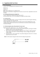
6.5 Remote Control Operation There are two methods for remotely controlling current and voltage adjustments. Current must be controlled for both methods otherwise the unit will default to CC mode. 6.5.1 REMOTE CONTROL – METHOD 1: Using two external DC voltage sources Remote Socket Pin Assignment for external variable voltage source PIN FUNCTIONS REMARKS 1 Internal DC +5V Lower than 50mA 2 Voltage adjust 0 to 5V 3 Current adjust 0 to 5V 4 Ground 5 Output OFF Short to ground 6 N.A. 7 N.A. 8 N.A.
6.5.3 Remote Control Output ON/OFF Remote output ON/OFF control can be activated in any of the modes Normal, Preset, Set, and Remote. Review the conditions below: By default, Pin 5 is open and the output is ON. Shorting Pin 5 to Pin 4 (ground) switches the output OFF. When the output is OFF, the C.V. & C.C. LEDs will flash. The present output voltage and current setting will be shown on the panel meter.
8.1 External Timed Program Window Clear Table: Delete all data in the Display Table and prepare for new data entry. Run (Stop): To run and stop the Timed Program. Running Cycle: Enter the number of desired running cycles here. The numerical range for cycling is 0‐999. Note that the maximum cycles can be set to ‘infinite’ when “0”cycles is entered. The External Timed Program allows the user to set the output either ON or OFF by selecting the boxes in the last column. 8.
9. Appendix – Additional Operational Examples Examples of Func A/B/C and Wave Form Generator Features These examples are continued from Examples 1 and 2 in Section 6.2 earlier in this guide. Example 3 ‐ Irregular waveform Set A= 5V, B= 10 V Set Δt a‐b = 1 second, Set Δt b‐a = 2 seconds Set Func. A = 3 seconds, Set Func.B = 3 seconds Example 4 ‐ Irregular waveform Set A= 5V, B= 10 V Set Δt a‐b = 2 second, Set Δt b‐a = 2 seconds Set Func. A = 2 seconds, Set Func.
10.Specifications Output Variable Output Voltage (Limited to O/P 160W) 0 ‐ 42VDC Variable Output Current (Limited to O/P 160W) 0 ‐ 10A Nominal Output Power (42V / 3.8A) 160W Preset Outputs Preset 1 (P1) Voltage: 5V ±0.2V, Current: 10A ±0.2A Preset 2 (P2) Voltage: 13.8V ±0.2V, Current: 10A ±0.2A Preset 3 (P3) Voltage: 20V ±0.2V, Current: 4.0A ±0.
Switching Frequency 45‐55 KHz~ Tracking Over Voltage Protections O/P 0‐10V: Set Voltage+ (1.0 ±0.3V) O/P 10‐42V: 105‐125% of set voltage Power Factor Control Power factor correction: >0.91 at optimal load Cooling Method Natural Convection Leakage Current ≤2mA Protections Adjustable upper voltage limit, Adjustable upper current limit, Short Circuit, Overload, Over Temperature , Tracking OVP Input Fuse T3.15AL250V Safety & EMC Safety Standard CE: EN 61010 Withstanding Voltage I/P‐O/P: 3.0KVac, I/P‐F/G: 1.
11.Troubleshooting OUP: Over Voltage Protection This unit has a built‐in tracking over voltage protection feature. In the event of output voltage becoming greater than the set value (see specified range from specifications table), protection will be triggered and the output power will be cut off and OUP warning appears as below. To reset the warning, switch off the unit and remove all loading. Switch the unit back on again and it should resume normal operation.