USER GUIDE Cable Tester and Digital Multimeter Model CT40
Introduction Congratulations on your purchase of the Extech CT40. The CT40 is a cable tester which uses a transmitter/receiver to allow for wire identification of an individual core to the end of a multi-core cable .The meter’s digital multimeter functions provides for easy measurement of AC/DC Voltage, AC/DC Current, Resistance, Continuity and Diode check. This device is shipped fully tested and calibrated and, with proper use, will provide years of reliable service.
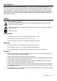
Meter Description 1. Low Battery Indicator -Receiver 2. Receiver Alligator Test Leads 3. Operation Indicator -Receiver 4. On/Off Switch -Receiver 5. Hold Switch – Digital Multimeter DMM Input Jacks 7. Max Button – Digital Multimeter Mode 8. Mode Button – Digital Multimeter Mode 9. LCD Display – Multimeter Mode 14 3 13 4 12 11 10 Mode 6. 2 1 15 16 5 9 8 7 6 10. Rotary Switch – Multimeter Mode 17 11. ID Test Button –Continuity Beep Test 12.
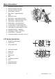
Operation Transmitter and Receiver Cable Tester Operation 1. Press down the receiver’s ON/OFF switch. The upper blue display will indicate “00” and the OP LED should light. 2. Press down the transmitter’s ON switch. The OP LED will flash. 3. Connect one of the transmitter’s alligator clips (CH1 to CH16) to each core (wire) of the cable under test. 4. Connect the transmitter’s “COM” reference lead (black alligator) to a known common for all cables, such as ground or cable sheath. 5.
Digital Multimeter Functions AC/DC Voltage Measurements 1. Insert the black test lead into the negative COM terminal and the red test lead into the positive V terminal. 2. Set the rotary function switch to VAC or VDC position. 3. Connect the test leads in parallel to the circuit under test. 4. Read the voltage measurement on the LCD display. CAUTION: Do not measure AC/ DC voltages if a motor on the circuit is being switched ON or OFF. Large voltage surges may occur that can damage the meter.
Continuity Check WARNING: To avoid electric shock, never measure continuity on circuits or wires that have voltage on them. 1. Set the function switch to the 2. Insert the black lead banana plug into the negative (-) jack (COM) and the red test lead banana plug into the positive (+) jack (). position. 3. Press the MODE button until the 4. Touch the test probe tips to the circuit or wire you wish to check. symbol appears in the display. 5.
Maintenance REPLACING THE FUSES WARNING: To avoid electric shock, disconnect the test leads from any source of voltage before removing the fuse cover. 1. Disconnect the test leads from the meter. 2. Remove the battery cover (two “B” screws) and the battery. 3. Remove the four “A” screws securing the rear cover. 4. Lift the center circuit board straight up from the connectors to gain access to the fuse holders 5. Gently remove the old fuse and install the new fuse into the holder. 6.
Specifications Max input voltage Diode Test Continuity Check Display Over range indication Polarity Low Battery Indication Input Impedance AC Response ACV Bandwidth Auto Power Off Fuse Batteries Operating Temperature Storage Temperature Weight Size Standards 600V AC/DC Test current 1mA max., open circuit voltage of 1.5V typical Audible threshold between 15Ω and 200Ω 2000 count 3 -1/2 digit LCD LCD displays “OL” Minus (-) sign for negative polarity. “BAT” symbol indicates low battery condition. >7.
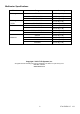
Multimeter Specifications Function DC Voltage AC Voltage 50-60Hz DC Current AC Current Resistance Range Accuracy 200mV, (0.5% rdg + 3d) 2.000V, 20.00V, (1.0% rdg + 3d) 200.0V, 600V (1.0% rdg + 3d) 2.000V, 20.00V (1.0% rdg + 5d) 200.0V, 600V (1.5% rdg + 10d) 200.0µA, 2000µA (1.5% rdg + 3d) 20.00mA, 200.0mA (2.0% rdg + 3d) 200.0µA, 2000µA (1.8% rdg + 8d) 20.00mA, 200.0mA (2.5% rdg + 8d) 200.0 (0.8% rdg + 5d) 2.000k, 20.00k, 200.0k (1.2% rdg + 3d) 2.000M (2.