User Manual Battery Capacity Tester Model BT100 Additional User Manual Translations available at www.extech.
Introduction Thank you for selecting the Extech Model BT100. The Battery Tester is designed for measuring the internal resistance and output voltage of batteries including lead storage cells, nickel-cadmium batteries, lithium-ion batteries, and nickel-metal hydride batteries. This device is shipped fully tested and calibrated and, with proper use, will provide years of reliable service. Please visit the Extech Instruments website (www.extech.com) to check for the latest version of this User Guide.
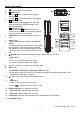
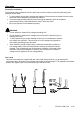
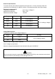
Meter Description 1. Power button: Power ON/OFF 2. R READ button: Press R button to start manually logging readings. Press R READ button again to stop logging. 3. M MEMORY button: Under the manual logging mode, the tester stores a single set of logged readings to the memory by pressing M MEMORY button. Press and hold M MEMORY button for 2 seconds to enter continuous (automatic) logging mode. Press again to stop logging. 4. V-RANGE button: Select the voltage range. (4V, 40V) 5.
Display Description 1. Measured resistance reading (or High/Low resistance limit when setting up the comparator) 2. Measured voltage reading (or High/Low voltage limit when setting up the comparator) 3. The comparator set number (there are 99 sets total) 4. The memory location for manually logged data.
Operation Preparation and Safety The following safety information must be observed to ensure maximum personal safety during the operation of this tester. To avoid electric shock when replacing the batteries: Disconnect the test leads from the device under test before attempting to replace the batteries. Check the battery polarity carefully when inserting the batteries. Refer to the battery replacement section (under Maintenance) later in this User Guide. Be sure to dispose of used batteries properly.
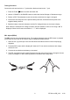
Testing Procedure Connect the red test lead to the “+” jack and the black test lead to the “-” jack. 1. Press the Power button to switch the tester ON. 2. Use the V-RANGE or Ω-RANGE buttons to select the desired Voltage or Resistance range. 3. Perform a REL Zero adjustment (see next section) each time the range is changed. 4. Connect the red test probe to the positive battery terminal, and the black test probe to the negative battery terminal. 5.
Comparator (99 sets) The comparator function compares the measured values with preset High and Low limit values for internal resistance and threshold voltage level, and determines the range that the measurement should fall into. Then, according to the following conditions, switches ON the corresponding LED, and sounds an audible alert as shown in the table below for the WARNING and FAIL conditions. Comparator Settings 1. Press and hold the SET button for 3 seconds then release, the display will show COMP.
Datalogging Manual Data Logging (999 sets) 1. Log readings one at a time to the internal memory by pressing the M MEMORY button. “DATA M NO XXX” will appear on the LCD for one second to indicate the memory location. 2. Press R READ button to review logged readings. The display will show “DATA R NO XXX”. 3. Use the and buttons to scroll the logged readings. 4. Press R READ again to discontinue viewing the logged readings. Continuous Data Logging 1.
Specifications Resistance measurement method Four (4) terminal Kelvin connections A/D conversion Dual slope Displays Dual LCD for measurements and programming icons Datalogger Sampling rate 1 to 255 seconds (interval time between logged readings) Open-circuit terminal voltage 3.
Electrical Specifications To ensure accuracy the ambient temperature should be 23°C ± 5° with a humidity of 80% RH (maximum) non-condensing. In addition, perform a Zero adjustment after each range change. Resistance measurements Temperature coefficient: Measurement frequency: Measurement burden voltage: (±0.1% rdg ± 0.5digits)/°C 1KHz ± 10% 1.5mVAC Range Resolution Measurement current 40mΩ 10µΩ 37.5mA approx. 400mΩ 100µΩ 3.75mA approx. 4Ω 1mΩ 375µA approx. 40Ω 10mΩ 37.5µA approx.
Maintenance Cleaning 1. Repair or service not covered in this User Guide should be performed by qualified personnel only. 2. Periodically wipe the case with a dry cloth; do not use abrasives or solvents. Battery Check & Replacement The symbol will be displayed when the batteries need replacement. 1. Disconnect the test leads from the meter and from devices under test 2. Switch OFF the power to the tester 3. Open the battery compartment cover with a screw driver 4.