User's Guide Vane Thermo-Anemometer Datalogger Model 451126 Introduction Congratulations on your purchase of Extech's Thermo-Anemometer Datalogger. This Vane-type Anemometer can indicate Air Velocity in five units of measure: Feet per minute, Meters per second, Miles per hour, Kilometers per hour, and Knots with Temperature o o displayed in C or F units. The meter can also display air flow in CFM or CMM.
Specifications General Specifications Display Dual 4-digit (9999 count) Multi-function LCD Data hold Locks latest reading on the LCD display Sensor Structure Air velocity sensor: Conventional twisted vane arm with low friction (sapphire) ball bearing. Temperature sensor: K-type thermocouple built into vane.
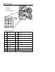
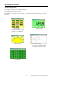
Meter Description 1. LCD Display 2. Vane Sensor 3. ON/OFF Key 4. RS-232 Connector 5.
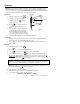
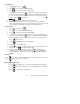
Operation NOTE: For all air velocity or flow measurements, the air should pass through the vane from back to front. The rear of the vane can be found by locating the mounting nut. The front of the vane has the engraving "ANEMOMETER". For more accurate results, maintain o a 20 axis of air direction with the rear of the vane (refer to Fig.2). Side view of Vane Air Velocity 1. 2. Power the meter by pressing . 20 Select Air Velocity measurement function by pressing o Air direction .
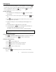
2/3Vmax Air Flow 1. Power the meter by pressing 2. Press to select Air Flow. FLOW will display. 3. Press to select the desired units (CFM, CMM). 4. . The previously stored area value will be displayed on the upper LCD display line. To enter a new area value press . The lower display line will blank waiting for the user to program new data. Use the numeric keys to enter a new area value in square feet. Press when finished. 5. Press 6. Determine the direction of the air to be measured.
Datalogging Instantaneous (One-Shot) Datalogging To record one data point at any desired time, set the sampling rate = 0 by pressing in the VEL mode. The previously stored reading will be displayed on the upper LCD line. Enter a '0' sampling time and then press . Now, each time is pressed, the present reading will be stored in non-volatile memory. Automatic Datalogging 1. Set the Sampling rate for datalogging by pressing . The previous sample rate will appear. 2.
Software The 451126 software lets the user: • Download logged recordings from the meter’s memory • Record to the PC • Graphically display readings from the meter System Requirements Hardware Requirements: 486 PC or better with COM 1 and COM 2 Serial ports Operating System Compatibility: Windows TM 95/98/NT/2000/XP Hardware Connection The IR Thermometer connects to a PC with the supplied DB-9 to DB-9 interface cable.
Starting the Software 1. Run the program by opening the program named “Flow Anemometer”. Flow Anemometer is in the programs folder of your Windows software. 2. Wait for the program to initialize and select COM 1 or 2 as required. The program will load and the main display will appear. A red NO COM icon will flash on the bottom right hand side of the display. 3. Press and hold then power on the meter by pressing The RS232 icon will appear on the upper right hand side display of the meter.
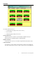
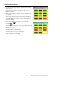
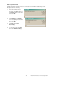
Operating the Software Graphical Display Mode The display command offers 5 different displays. Click Display on menu bar to select. Click Option to set Upper and Lower Limits. The software will then flag readings exceeding the limits. Main Display Digital Display Click Reset button on main display to clear Min/Max Analog Display Graphical Display Click Scale in Graphical Mode to change x and y axis scale. List Display 9 Model 451126 Version 1.
Data Acquisition Mode In data acquisition mode the meter is connected to a PC with the data being saved directly to the PC’s memory. 1. In the Flow Anemometer program, click File, and then click Name. Enter a file name and click OK 2. Click Option then Sample, enter a sampling interval and then click OK 3. Click File then Start Recording. 4. To stop the meter click File then click End Recording. 10 Model 451126 Version 1.
Viewing Files Files can be view in table form or they can be plotted on a graph. Viewing in a table: 5. In the Flow Anemometer program, click File, and then click View File. 6. When the View screen opens click File then click Open. 7. In the Look in list, click the drive, folder, or Internet location that contains the file you want to open. 8. In the folder list, locate and open the folder that contains the file. The File will then open. Click File then Print to print records Plotting a graph 1.
Downloading Logged Data to the PC Note: The RS232 communication symbol should NOT be displayed in the LCD when downloading. 1. Click Datalogger on the menu. The Datalogger Anemometer screen will open. 2. Click the Download button. The Log File screen will open. Enter a File name and click OK button. The Status screen will open. Status screen will count up the number of readings being transferred. 3. Press to initiate data transfer from the meter to the PC 4. When transfer is completed click OK. 5.
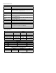
Useful Equations and Conversions Area equations Circular Duct Rectangular Duct H Area = W x H R A= π R (A= 3.14 x R x R) 2 W Cubic equations 3 2 CFM (ft /min) = Air Velocity (ft/min) x Area (ft ) 3 2 CMM (m /min) = Air Velocity (m/sec) x Area (m ) x 60 Units Conversion Table 1 m/s m/s ft/min knots km/hr mph 1 196.87 1.944 3.6 2.24 1 ft/min 0.00508 1 0.00987 0.01829 0.01138 1 knot 0.5144 101.27 1 1.8519 1.1523 1 km/hr 0.2778 54.69 0.54 1 0.6222 1 mph 0.4464 87.89 0.
Battery Replacement The low battery indicator appears on the LCD display when it is time to replace the 9V battery, which powers the meter. To replace the battery: a. Turn the meter off. b. Remove the battery compartment screw and remove the battery compartment cover. c. Replace the 9V battery and reinstall the compartment cover. d. Fasten the compartment screw 14 Model 451126 Version 1.
Appendix A: Real-time Datalog-to-PC transfer Byte 1 0D (Hex) Byte 9 Byte 2 bit4: Velocity OL, bit5 Area OL, bit 6: Byte 10 Temp OL Byte 3 0: m/s, 1: ft/min, 2: knots, 3: km/hr, 4: MPH Byte 11 Byte 4 bit2: MAX, bit3: MIN, bit4: 0:VEL 1:FLOW, bit 5: 0: DEG C, 1:DEG F, bit7: RS-232 enabled Byte 5 bit0: 0:CMM, 1: CFM, bit3: low batt, bit4: Temp OL, bit5: AVE, bit6: 2/3Vmax, bit7: Instant Byte 6 Lower LCD decimal, bit0: x100, bit1: x10, bit2: x1, bit3: dp1 (rightmost), bit4: dp2, bit5: dp3 (leftmost) Byte 7 Upp
Warranty EXTECH INSTRUMENTS CORPORATION warrants this instrument to be free of defects in parts and workmanship for one year from date of shipment (a six month limited warranty applies on sensors and cables). If it should become necessary to return the instrument for service during or beyond the warranty period, contact the Customer Service Department at (781) 890-7440 ext. 210 for authorization or visit our website at www.extech.