User's Guide Digital Multimeter plus IR Thermometer Extech 450 Patented
Introduction Congratulations on your purchase of the Extech 450 (part number EX450) Autoranging Multimeter plus IR Thermometer. This meter measures AC/DC Voltage, AC/DC Current, Resistance, Capacitance, Frequency, Duty Cycle, Diode Test, and Continuity plus NonContact IR Temperature. Proper use and care of this meter will provide many years of reliable service.
CAUTIONS Improper use of this meter can cause damage, shock, injury or death. Read and understand this user manual before operating the meter. Always remove the test leads before replacing the battery or fuses. Inspect the condition of the test leads and the meter itself for any damage before operating the meter. Repair or replace any damage before use. Use great care when making measurements if the voltages are greater than 25VAC rms or 35VDC. These voltages are considered a shock hazard.
OVERVOLTAGE CATEGORY III This meter meets the IEC 610-1-2001 standard for OVERVOLTAGE CATEGORY III. Cat III meters are protected against overvoltage transients in fixed installation at the distribution level. Examples include switches in the fixed installation and some equipment for industrial use with permanent connection to the fixed installation. SAFETY INSTRUCTIONS This meter has been designed for safe use, but must be operated with caution.
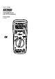
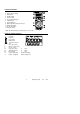
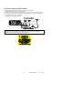
Controls and Jacks 1. 2. 3. 4. 5. 6. 7. 8. 9. 10. 11. 12. IR Thermometer and laser pointer 2000 count LCD display HOLD button SELECT button Function switch mA, uA and A input jacks COM input jack Positive input jack MAX hold button (voltage and current) BACKLIGHT button Laser pointer button Protective holster Note: Tilt stand and battery compartment are on rear of unit.
Operating Instructions WARNING: Risk of electrocution. High-voltage circuits, both AC and DC, are very dangerous and should be measured with great care. 1. ALWAYS turn the function switch to the OFF position when the meter is not in use. 2. If “OL” appears in the display during a measurement, the value exceeds the range you have selected. Change to a higher range. NOTE: On some low AC and DC voltage ranges, with the test leads not connected to a device, the display may show a random, changing reading.
AC VOLTAGE MEASUREMENTS WARNING: Risk of Electrocution. The probe tips may not be long enough to contact the live parts inside some 240V outlets for appliances because the contacts are recessed deep in the outlets. As a result, the reading may show 0 volts when the outlet actually has voltage on it. Make sure the probe tips are touching the metal contacts inside the outlet before assuming that no voltage is present. CAUTION: Do not measure AC voltages if a motor on the circuit is being switched ON or OFF.
AC CURRENT MEASUREMENTS CAUTION: Do not make current measurements on the 20A scale for longer than 30 seconds. Exceeding 30 seconds may cause damage to the meter and/or the test leads. 1. Insert the black test lead banana plug into the negative COM jack. 2. For current measurements up to 2000µA AC, set the function switch to the yellow µA position and insert the red test lead banana plug into the µA/mA jack. 3.
CONTINUITY CHECK WARNING: To avoid electric shock, never measure continuity on circuits or wires that have voltage on them. 1. Set the function switch to the green Ω position. 2. Insert the black lead banana plug into the negative COM jack. Insert the red test lead banana plug into the positive jack. 3. Press the SELECT button to indicate” "and “Ω” on the display 4. Touch the test probe tips to the circuit or wire you wish to check. 5.
NON-CONTACT TEMPERATURE MEASUREMENTS 1. Set the function switch to the red IR Non-Contact ºC or ºF position. 2. Point the meter at the surface to be measured. 3. If needed, press the red IR Laser Pointer button to locate the exact spot being measured. 4. The area of the surface to be measured must be larger than the spot size as determined by the distance to spot size specification. 5. Read the temperature in the display. WARNING: Do not directly view or direct the laser pointer at an eye.
DISPLAY BACKLIGHT Press and hold the HOLD key for >1 second to turn on or off the display backlight function. Note: The HOLD feature will activate when the Backlight is turned on. Press the HOLD key again to exit Hold. MAX Press the MAX button to activate the MAX feature in the voltage or current functions. The display will hold the maximum reading and will update only when a reading higher then the currently displayed reading occurs. Press the MAX button again to disable the feature.
Specifications Function DC Voltage Range 200mV Resolution 0.1mV 2V 20V 200V 1000V 0.001V 0.01V 0.1V 1V 2V 0.001V (1.0% reading + 4 digits) (2.5% reading + 8 digits) 20V 200V 750V 0.01V 0.1V 1V (1.5% reading + 4 digits) (3.0% reading + 8 digits) (2.0% reading + 6 digits) (3.5% reading + 8 digits) 200A 0.1A 2000A 20mA 200mA 2A 20A 1A 0.01mA 0.1mA 0.001A 0.01A 200A 0.1A 2000A 20mA 200mA 2A 20A 1A 0.01mA 0.1mA 0.001A 0.01A AC Voltage DC Current Accuracy (0.
Function Resistance Temp (IR) Range Resolution 200 0.1 (0.8% reading + 4 digits) 2k 0.001k (0.8% reading + 2 digits) 20k 0.01k 200k 0.1k 2M 0.001M 20M 0.01M -58 to 518F 1F -50 to270C 1C Accuracy (1.0% reading + 2 digits) (3.0% reading + 5 digits) 2.0% reading or 2C, 4 F NOTE: Accuracy specifications consist of two elements: (% reading) – This is the accuracy of the measurement circuit. (+ digits) – This is the accuracy of the analog to digital converter.
Maintenance WARNING: To avoid electrical shock, disconnect the meter from any circuit, remove the test leads from the input terminals, and turn OFF the meter before opening the case. Do not operate the meter with an open case. This MultiMeter is designed to provide years of dependable service, if the following care instructions are performed: 1. KEEP THE METER DRY. If it gets wet, wipe it off. 2. USE AND STORE THE METER IN NORMAL TEMPERATURES.
REPLACING THE FUSES WARNING: To avoid electrical shock, disconnect the meter from any circuit, remove the test leads from the input terminals, and turn OFF the meter before opening the case. Do not operate the meter with an open case. 1. Disconnect the test leads from the meter. 2. Remove the protective rubber holster. 3. Remove the battery cover (two “B” screws) and the battery. 4. Remove the four “A” screws securing the rear cover. 5.