INSTRUCTION MANUAL Model 407355 Datalogging Noise Dosimeter with PC Interface • 5 Event Data Storage • Personal noise accumulation tests • 70 to 140dB sound level measurements • RS-232 PC Interface 1. INTRODUCTION Congratulations on your purchase of Extech’s Dosimeter. This professional meter, with proper care, will provide years of safe reliable service. 1 407355 Ver. 1.
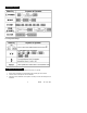
. SPECIFICATIONS Applicable Standards Microphone Display DOSE Range Criterion Level Threshold Level Exchange Rate High Level Detector Peak Flag Sound level range Accuracy Frequency Weighting Frequency Response Response time Operating Temp/Humidity Storage Temp/Humidity Power supply Dimensions Weight Accessories ANSI S1.25-1991 A-weighting; ISO-1999, BS 64021983 1/2-inch electret condenser microphone w/ 31” cable Multifunction 4-digit LCD Display .
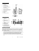
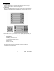
. METER DESCRIPTION 1. Microphone 2. LCD Display 3. Power ON/OFF key 4. RUN / Left Arrow key 5. SPL, DOSE, TIME Mode and Left Arrow key 6. Event / Up Arrow key 7. Real time clock / Right Arrow key 8. Reset key (clears Event data) 9. Calibration screw 10. Battery Cover 11. Belt clip 12. PC interface connector 4. DISPLAY DESCRIPTION 1. 2. %DOSE icon Peak detector (> 140dBA) icon 3. TIME display icon 4. Sound Level measurement icon 5. High level warning icon (> 115dBA) 6.
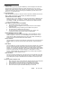
6. OPERATING INSTRUCTIONS 6. 1 Meter Power Power the meter by pressing the green POWER key, all of the display annunciators will appear briefly and the default configuration values will appear one by one. The main display screen will then appear. If the meter does not power correctly, check the batteries. To remove meter power, press and hold the green POWER key until the meter counts down (3, 2, 1, 0) and powers OFF. 6.
7. REFERENCE TABLES 7.1 Basic Operation 7.2 Configuration Settings 8. CALIBRATION PROCEDURE NOTE: A Sound Level Calibrator, available from Extech, is required. 1. 2. 3. Set the meter to display sound level (dBA) with a SLOW (S) Time constant. Insert the meter’s microphone into the Calibrator. Adjust the meter’s calibration screw (bottom of meter) to match the dB output of the Calibrator. 5 407355 Ver. 1.
9. METER CONFIGURATION SETTINGS To change the meter’s default settings, first remove meter power. Press and hold the RESET key while applying meter power. The current month (3-letter format) will briefly appear (let go of the RESET key now) followed by Lc (Criterion Level) with a blinking value. Change the value using the Up/Down arrow keys (MODE/EVENT keys). Scroll through the parameters using the right arrow (CLOCK) key. Change their settings using the Up/Down arrow keys.
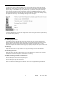
11. PC INTERFACE 11.1 Hardware Setup Connect the RS-232 5-pin male connector to the DOSE Meter. Connect the 9-pin connector to the PC COM Port. Refer to the diagram below. 11.2 Cable/Wiring Refer to the wiring diagram below for any wiring questions. Keep in mind that Hardware Handshake must be disabled; RTS must be pulled low via software in order to achieve successful communication. If COM2 is used on your PC, you will need a 9- to 25-pin (female) adapter (included).
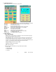
11.4 DOSE Meter Windows Refer to diagrams below for Main Menu Control Panel Sample: Last Time: File Name: Response: Value: Exchange rate: Minimum: Maximum: Reset: Criterion level: Range: Threshold level: The value under SAMPLE is the rate at which readings are recorded. LAST TIME is the time of day of the last recorded reading File where data are stored (F) Fast and (S) Slow modes The text under VALUE is the Dosimeter measurement. There are four exchange rates (3, 4, 5, and 6dB).
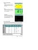
2. ‘DISPLAY’ MENU HEADING Analog If this option is selected or CTRL+A is pressed, a window, which emulates an analog meter, appears on the screen. See diagram. Digital If this option is selected or CTRL+D is pressed, a window, which emulates the Dosimeter LCD display, appears on the screen. See diagram. Sound Wave If this option is selected, a window appears which will rapidly plot dB over time. The horizontal scale is 4 seconds and the display will plot at approximately 200mS per measurement. 3.
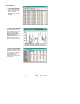
11.6 GRAPH MENU 1. ‘LIST’ MENU HEADING Lists the date, time, Value (SPL or %DOSE), TWA, criterion level (CL), Response, and exchange rate (ER) 2. ‘GRAPH’ MENU HEADING When selected, a window, which emulates a strip chart recorder appears. This feature can only be used with “real time” data acquisition. Data previously stored in a file can not be graphed using this program. 3. ‘EVENT’ MENU HEADING Download and save the five independent events stored in the E1-E5 memory locations.
4. ‘AVERAGE’ MENU HEADING — Displays the average Sound Level. Time interval can be set from 2 to 60 seconds. — Average data can be saved to file. See below: 12. DOSIMETRY GLOSSARY OF TERMS Criterion Level Exchange Rate Threshold Time Weighted Average Constant sound level that, if applied for 8 hours, would accumulate the allowable dose of 100% Number of dB required to double the allowable exposure duration.
14. WARRANTY EXTECH INSTRUMENTS CORPORATION warrants this instrument to be free of defects in parts and workmanship for one year from date of shipment (a six month limited warranty applies on sensors and cables). If it should become necessary to return the instrument for service during or beyond the warranty period, contact the Customer Service Department at (781) 890-7440 for authorization. A Return Authorization (RA) number must be issued before any product is returned to Extech.