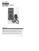
User's Guide True RMS Power MultiMeter Model 382860 INTRODUCTION Congratulations on your purchase of the Extech Model 382860 True RMS Power MultiMeter. Four LCD displays offer four simultaneous readings e.g.
Safety Notes • • • • • • • • • • • • • • • • • The multimeter is EMC-tested and corresponds to the following EG-standard: 89/336/EWG This unit is constructed and checked according to DIN 57 41 Part 1/VDE 0411 Part 1, Safety Requirement for Electronic Measuring Units and Over-voltage Category II (IEC1010-2). This multimeter may only be used in fuse lines which are protected to 15A. The voltage must not exceed 250 VDC/VAC and the maximum load must not exceed 4000 VA.
SAFETY SYMBOLS This symbol adjacent to another symbol, terminal or operating device indicates that the operator must refer to an explanation in the Operating Instructions to avoid personal injury or damage to the meter. WARNING This WARNING symbol indicates a potentially hazardous situation, which if not avoided, could result in death or serious injury.
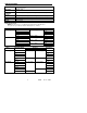
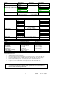
SPECIFICATIONS General Specifications Display One Main and three Sub 3-3/4-digit (3999 count) LCDs plus 40segment bargraph Max. Input DC/AC : 20A Current o Operating 0 to 104 F (0 to 40°C), relative humidity: <75%, not wetting Conditions o Storage 0 to 122 F (-10 to 50°C), relative humidity: <76%, not wetting Conditions Power 9V Battery: NEDA 1604 9 V or 6F22 Dimensions 7.36x3.3x1.34” (187x84x34mm) Weight 9.
Mode Frequency (Sensitivity:>300mVrms) Temperature Measuring Range 4kHz 40kHz 400kHz 4MHz 40MHz Accuracy ± (0.1% + 2dgts) -40°C to 200°C Capacitance Diode Test Continuity Check Mode Power Measurements AC Current AC Voltage True Power True Power Phase angle (cosine) Power Factor Range 400Ω 4k Ω 40k Ω 400k Ω 4M Ω 40M Ω 1Hz 10Hz 100Hz 1kHz 10kHz 1° C ± (3%+5dgts) +200°C to 1200°C Mode Resistance Resolution ± (3%+2dgts) Accuracy ± (0.5% + 1dgts) ± (1% + 2dgts) <20MΩ ± (5%) >20MΩ ±2.
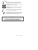
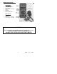
METER DESCRIPTION Function Keys: Power ON/OFF Key FUNCTION Select Key Set/Reset Key AC/DC Ohm/Continuity Key UP Key DOWN Key Backlight Adjust Button U • • • • • • • Input Terminals 20-A Input Socket mA-input COM Socket (- Terminal) V-ohm Socket (+ Terminal) U • • • • WARNING The power adaptor included with this item is designed to be used with the Extech Model 382860 Power Multimeter. DO NOT USE IT WITH ANY OTHER MULTIMETER 6 382860 Ver. 2.
OPERATING INSTRUCTIONS Quick Start • Connect the test leads to the meter • Press the “ON/OFF” key to power the meter. • Turn the rotary function switch to the desired measurement position. The meter is now ready for “normal” measurement operation. • To select an advanced function, press the FUNCTION key. The available functions will appear on the top of the LCD display. Press FUNCTION again to scroll through this function list. Press the SET/RESET key to select an advanced function.
• • • mA-Measuring Socket For DC/AC mA current measurements below 400mA, insert the Red test-lead to this terminal. COM (Common or Negative Input Terminal For all measurements, except capacitance, temperature and transistor measurements, the Black test lead is connected here V/Ohm-Socket For measurements of voltage, frequency, resistance, continuity, diode and logic, insert the Red test lead into this terminal.
MEM (Memory): Up to 10 measurements (0 to 9) can be stored and recalled. Press the FUNCTION key five times then press the SET/RESET key once to store the present measurement value in the first available memory location. The memory location number will flash to the upper left of the left-most sub-LCD. The memorized reading is shown on the center sub-LCD. Use the UP/DOWN keys to scroll to the next free memory location. Take another measurement and press the SET/RESET key to store it.
MEASUREMENT INSTRUCTIONS Voltage AC/DC Measurements (True RMS for AC Voltage) Attention: Never exceed the maximum input limits (1000VDC or 750 VAC rms).Keep hands away from circuits where 25 VAC rms or 35 VDC exists. To measure DC / AC voltage proceed as follows: 1. Set the rotary function switch to the desired position (mV or V) 2. Press the DC/AC key until the desired units are displayed (AC or DC). 3. Connect the test-lead tips to the object under test (load, circuit etc.) 4.
Resistance Measurements Attention: Make sure all objects, circuits and components under test are NOT powered! 1. 2. 3. 4. 5. 6. Set the rotary switch to the Ohms position. Press the AC/DC key so that the continuity musical symbol does NOT appear on the LCD. Connect the test-leads to the device under test. Ensure that all power is removed from devices under test. Auto Range selects the appropriate range automatically. Normally the resistance of the test-leads can be disregarded (approx. 0.1 to 0.2 Ohm).
Frequency Measurement Attention: Observe the max. input limits. Never connect voltages over 750 VDC/VAC rms. It is hazardous to touch the terminals or probe tips when measuring voltages > 25VAC/35 VDC. Disconnect the test-leads from the contact points when measuring voltage (over 25 VAC or 35 VDC) and before changing the meter function and range 1. 2.
Temperature Measurement The main display will show the temperature in degrees centigrade, while the middle sub-display will show the temperature in degrees Fahrenheit 1. Select “TEMP” with the rotary function switch. 2. Insert in the temp probe into TEMP/CAP socket, observe the correct polarity (narrow and wide tongue). Type K thermocouple probes are to be used exclusively. Logic Test This function allows logic level tests in digital circuits. 1. Switch the meter power ON. 2.
POWER MEASUREMENTS For the measurement of power, the Power Adaptor (included) is required. This adaptor consists of a three-prong plug and three-prong socket on one end (for connection to loads under test) and a multi-plug on the other end (for insertion into meter's input terminals). WARNING The power adaptor included with this item is designed to be used with the Extech Model 382860 Power Multimeter. DO NOT USE IT WITH ANY OTHER MULTIMETER Test Procedure 1.
Three Modes of Power Measurement Displays There are three modes of Power Measurement Displays. These modes have different Main LCD and Sub-LCD displays related to power. Mode 0 is the initial mode that the meter will be in when the POWER position is selected with the Rotary Switch. A zero will display to the upper left of the left-most sub-LCD indicating Mode 0. Use the UP and DOWN arrow keys to scroll through modes 0 through 2.
Storing and Clearing Accumulated Measurement Data The meter memorizes accumulated reading data when the POWER position of the Rotary Switch has been changed to another function after Power measurements have been made (this activates the memory utility). To recall accumulated data, reselect POWER on the Rotary Switch, the meter displays stored data in EEPROM. To clear accumulated readings: Set the Cost per KW/H to 0000.0 in mode 2 (left sub-LCD display). General Power Measurement Notes: 1.
CMOS Signal Output Your meter is equipped with a “Function Generator” which supplies outputs of ten preset frequencies with a voltage max. of 3.3V. To “tap off” the signal, insert the enclosed signal adaptor into the capacitor socket, observing the correct polarity. The other end of the adaptor has two small alligator clips. To change the multimeter into a signal generator and to select the output frequency, follow these steps. 1. Select “SIG OUT” with the rotary function switch. 2.
PC INTERFACE Hardware Setup Connect the supplied RS-232C cable between the meter’s com port and the computer’s serial port. Power the meter and the computer and then load the software. Software for PC Interface Two data acquisition programs are included: a DOS version (ScopeView) and a Windows version (MultiView). Using the DOS Software Follow these steps to install and run the MS-DOS software. 1. Insert the supplied diskette in your computer’s 3 ½-inch floppy drive. 2.
MAINTENANCE Fuse Replacement Remove power to the meter and removal all connected cables and probes. Use a suitable Phillips screwdriver to carefully open the case. Remove the defective fuse(s) and replace it with a new one of the same type and nominal current (0.8A fast blow, 250 V); usual name: F 0.8A/250A or F 800Ma/250V. For the amperage range 20 A ultra rapid, 250V; usual name F 12A/250V (BUSSABC12). After the fuse has been exchanged close the cabinet.
Warranty EXTECH INSTRUMENTS CORPORATION warrants this instrument to be free of defects in parts and workmanship for 1 year from date of shipment (a six month limited warranty applies on sensors and cables). If it should become necessary to return the instrument for service during or beyond the warranty period, contact the Customer Service Department at (781) 890-7440 ext. 210 for authorization or visit our website at www.extech.