
User`s guide

382280-EU-EN v1.9 07/13
4
Operation
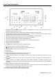
Preparation for use
1. Place the supply on a flat level surface.
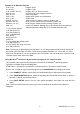
2. Select the input voltage using the switch on the rear of
the supply (see diagram above).
3. Make sure the sides and the back of the unit are not
blocked. Leave at least 2” (5 cm) of space for good
ventilation.
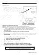
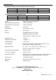
Basic Test Setup Diagram
Setting and Outputting Voltage and Current
NOTE: The 3.3V and 5V fixed outputs are always active when power is turned on.
NOTE: The power supply enters the STBY (stand-by) mode when the power is turned on. The output
values, time delay, and OVP are the same as they were before the power was turned off.
1. Connect the power supply output to the circuit or device under test before pressing the
OPER/STBY button.
2. Check that the displayed voltage and current output settings are as desired.
3. To change the values of voltage or current use the V/A button to move the underline cursor to first
digit of the voltage or current display, enter the value directly from the numeric keypad and then
press ENTER or:
a. Move the underline cursor to voltage or current with the V/A button,
b. Use the RIGHT arrow button to select the digit to change,
c. Use the UP/DOWN arrow buttons to change the digit value
d. Press the ENTER button to select the value.
4. To clear any programming entries, press the CE button.
5. Press the STBY/OPER button to enable the power supply output.
Note: If the output goes to zero, the current or voltage limit may be set too low.
6. To change the output values during operation, use the RIGHT & UP/DOWN buttons.
7. The user can monitor the output voltage by connecting a DMM as shown above.
Warning: When the unit is placed in STBY mode, the output is 0V; however the
output terminals are still physically connected to the internal circuit.
Line Voltage
Selector Switch