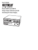
User's Guide Model 382275 and 382276 Single Output Laboratory Grade Switching DC Power Supply
Introduction Congratulations on your purchase of the Extech 382275 Single Output Laboratory Grade DC Power Supply. The dual action (coarse/fine tune) rotary encoder makes setting the voltage and current levels ever so smooth, precise and fast. Setting, changing, and checking the current limit level can be done easily without sparking the output poles. The remote control functionality allows the output power on/off, voltage & current to be adjusted without touching the front panel of the power supply.
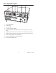
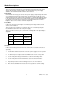
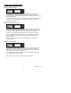
Power Supply Description 2 3 1 4 5 6 10 9 7 8 1. Power Switch ON/OFF 2. Voltage Display 3. Current Display 4. Constant Voltage Indicator LED 5. Rear Control Indicator LED (Switches On when in Preset, Remote Control or Set Mode) 6. Output Voltage Control Knob (Controls both the main and auxiliary output voltage) 7. Output Current Control Knob (Controls both the main and auxiliary output current) 8. Positive Auxiliary Output Terminal (Max 5 Amps) 9.
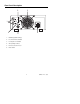
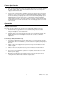
Rear Panel Description 3 2 1 6 1. 4 5 Main Output (Max 20 Amps) 2. P1, P2 and P3 Recall Switch 3. Cooling Fan for Ventilation 4. AC input Plug and Fuse 5. Remote Control Connector 6. Mode Switch 4 382275/6 V1.
Mode Descriptions Control Mode Selection There are four modes: Normal, Preset, Set and Remote Control mode for the power supply. Slide the Mode Selection Switch to the desired Mode. The power supply defaults to the Normal Mode with maximum current level CC. Normal Mode Normal Mode is the factory preset mode. The power supply’s output voltage and current are controlled by the dual action volume knobs. Push the knobs to toggle the coarse and fine tuning; notice the subtle changes in brightness of related LED.
Power Up Checks 1. First, check the rating label of the power supply and make sure it complies with the AC mains voltage. Next, set the Mode Switch located on the rear of the power supply to the Normal Position. 2. Listen for the cooling fan when switching on the power supply. The power supply performs a series of self test checks on startup which include testing the cooling fan. The fan will stop completely after a few seconds after running at high speed indicating that it is in good order.
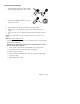
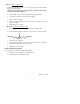
Remote Control (Voltage) 1. Remove the black portion of the remote control connector plug by removing the screw as shown. 2. Solder 3 wires (22AWG) to PORT 1, 2 & 4 of the 1 2 7 8 3 black portion as shown. 4 3. Ensure that the load is disconnected and the power supply is OFF. 4. Plug the remote connector plug into the remote control terminal of the power supply. 5. Secure the remote connector plug to the terminal socket by locking the connector ring.
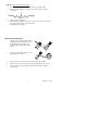
Method B : Using A 5Kohm Variable Resistor 1. Ensure that the load is disconnected and that the power supply is OFF. 2. Prepare a 5Kohm variable resistor and use the wires from Port 1, 2 and 4 as shown below: 2 1 4 5KΩ 3. Switch the power supply ON. 4. Adjust the 5Kohm variable resistor from one end to other end to check and verify the full output voltage range of the power supply. 5. Switch OFF the power supply. Remote Control (Current) 1.
Method A : Using A Voltage Source A variable external voltage source of 0 ~ 5V is fed into the remote control terminal to adjust the output current level. Warning!: Do not input voltages higher than 5V, otherwise the Over Voltage Protection (OVP) will be triggered. 1. Ensure that the load is disconnected and the power supply is OFF. 2. Use ONLY wires from port 3 (Positive) and 4 (Negative) 3. Switch on the power supply. 4.
Faults and Troubleshooting OUP: Over Voltage Protection oup C.V. A C.C. This unit has a built-in tracking over voltage protection feature. In the event of output voltage becoming greater than the set value (see specified range from specifications table), protection will be triggered and the output power will be cut off. (OUP warning appears) To reset the warning, power off the unit and remove all loading. Power the unit back on again to resume normal operation.
Specifications Output Voltage Regulation Current Regulation Meter Accuracy Tracking Over Voltage Protection Variable Output Voltage 1 to 30VDC Variable Output Current 1 to 20A Load (10 to 100% Load) 50mV Line (170 to 264VAC Variation) 20mV Load (90 to 10% Rated Voltage) 100mA Line (170 to 264VAC Variation) 50mA Ripple & Noise (peak-peak) Voltage 50mV Current Ripple & Noise (r.m.s.) 30mA Voltage Meter ±(0.2% +3 digits) Current Meter ±(0.
Maintenance and Repair Services Cleaning the meter housing Prior to cleaning the meter housing, disconnect the mains plug from the power outlet. Clean only with a damp, soft cloth and a commercially available mild household cleaner. Ensure that no water gets inside the equipment to prevent possible shorts and damage to the equipment. Calibration and Repair Services Extech offers repair and calibration services for the products we sell. Extech also provides NIST certification for most products.
Warranty EXTECH INSTRUMENTS CORPORATION (A FLIR COMPANY) warrants this instrument to be free of defects in parts and workmanship for one year from date of shipment (a six month limited warranty applies to sensors and cables). If it should become necessary to return the instrument for service during or beyond the warranty period, contact the Customer Service Department at (781) 890-7440 ext. 210 for authorization or visit our website www.extech.com for contact information.
382275/6 V1.