User Manual Earth Ground Resistance Tester Kit Model 382252 Additional User Manual Translations available at www.extech.
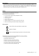
Introduction Congratulations on your purchase of the Extech 382252 Earth Ground Resistance Tester Kit. This device can measure Earth Ground Resistance (in 3 ranges), Earth Voltage and Resistance (up to 200kand AC and DC voltage. This device was designed to meet EN61010-1 safety standards. Careful care and use of this meter will provide years of reliable service.
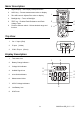
Meter Description 1. Digital Display – See Display Description below 2. HOLD key – Freezes measurement value on display 3. Zero ADJ control- Adjusts Zero value on display 4. Backlight key – Turns on Backlight 5. TEST key – Enables Earth Resistance and Earth Voltage Tests 2 6. Function Selector switch – Selects desired range and function 3 1 4 5 6 Top View 1. VC Input (Red) 2. P Input (Yellow) 3. COM / E Input (Green) 1 Display Description 1. Test status Icon 2.
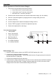
Operation ZERO Adjustment of Earth Resistance Ranges 1. Connect the long test leads to the meter as follows: a. Green lead to the 'E' terminal (Green jack) b. Yellow lead to the 'P' terminal (Yellow jack) c. Red lead to the 'C' terminal (Red jack) 2. Set the function selector switch to the desired measurement range. (20, 200, 2000Ω) 3. Short the 3 test leads together by clipping them all to a single earth ground rod. 4. Press the TEST key. 5.
Earth Ground Resistance test 1. Connect the 3 test leads to the meter (1) as follows: Green lead (2) to the 'E' terminal Yellow lead (3) to the 'P' terminal Red lead (4) to the 'C' terminal 2. Drive the Auxiliary Earth Bars P1 (6) & C1 (7) into the ground. Align the bars an equal distance apart to the existing Earth ground rod connection and in a straight line as shown in the diagram above.
200k Resistance Measurement 1. Connect the red test lead to the V(C) connector and the black test lead to the COM (E) connector. 2. Set the function selector switch to the 200kposition. 3. Connect the test probes to the circuit under test. 4. Note the displayed Resistance value. AC Voltage Measurement 5. Connect the red test lead to the V(C) connector and the black test lead to the COM (E) connector. 1. Set the function selector switch to the 750V AC position. 2.
Maintenance Battery Replacement ' appears on the LCD, the meter's batteries must be changed. When the low battery icon ' 1. Remove power and disconnect the test leads from the meter. 2. Remove the tilt stand from the rear of the meter. 3. Remove the 4 battery compartment screws with a Phillips head screwdriver. 4. Remove the battery compartment cover and replace the six 1.5V 'AA' batteries. 5. Affix compartment cover and tighten screw. 6. Reattach the tilt stand.
Measurement Specifications Measurement Earth Ground Resistance Earth Voltage Range Resolution Accuracy 20 0.01 ± (2% reading + 10 digits) 200 0.1 2000 1 0 to 200VAC Frequency: 40 to 500Hz 0 to 200kΩ ± (2% reading + 3 digits) 0.1V ± (3% reading +3digits) 0.1k ± (1% reading +2 digits) Resistance Overload Protection: 250 Vrms AC Voltage 0 to 750V 40 Hz to 400Hz Overload Protection: 750 Vrms, Input Impedance: 10M 0 to 1000V DC Voltage 1V ± (1.2% reading +10 digits) 1V ± (0.