
User Manual

4-Port PoE (PSE) Gigabit Ethernet PCIe Card
2
Due to the hot-plug feature of the PCI Express, the installation of the PCIe Quad
Channel Gigabit Ethernet card is quite straightforward.
1. Turn the system power OFF before installation!
2. Use static electricity discharge precautions. To avoid damaging any
components on the card, handle it by edges.
3. Remove the chassis cover from your computer
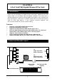
4. Since this Card needs 12V to generate PoE power to its RJ45 connectors,
please connect power supply cable to J2 (large 4-pin type) or J3 (SATA
15-pin type) power connectors
5. Locate an unused PCI Express slot (typically white and smaller) and
remove the corresponding slot cover from computer chassis.
6. Plug the Quad Channel Ethernet PCIe card to the unused PCI Express
expansion slot and attached the I/O card bracket to the computer chassis
screw.
7. Put the chassis cover back on the computer.
8. Turn ON the power of your computer and peripherals.
9. Proceed with Software Driver Installation.
10. Installing LAN cables
Connect the LAN cables to both RJ45 connectors of the Quad Channel
Ethernet PCIe card. Please check the LEDs’ status as follows:
The ‘
LINK(ACT)
’ LED will light if link on. However, the same LEDs will flash
when transferring data.
The ‘
PoE
’ LEDs will light up if a (PoE) PD is connected. In this case, the
48V DC power was applied on the LAN cable. Otherwise, if the ‘
PoE
’ LED
is off, the device is not a (PoE) PD and the LAN cable does NOT carry 48V
DC power on it.
LED Name
Color
LED Function
LINK(ACT)
Green
Steady on: Linked
Blinking: Transferring Data
PoE
Yellow
Steady on: PoE Enabled.
Off: PoE Disabled.
3. Installing the Gigabit Ethernet PCIe Card